
Assembly Properties - Component / Cavity Part Group Properties / Insert Group Properties
The database fields can only be modified if the Database Editor has been activated.
To display/modify the properties of an assembly, a cavity part group component or insert group,
-
right-click on the assembly / connector pin terminal group component in the Component Tree of the Database Window and select the Assembly Properties... / Cavity Part Group Properties... / Insert Group Properties... command from the displayed context menu. In this case, the component cannot be edited, the dialog only serves for information.
-
To edit the assembly / cavity part group component / insert group, right-click on the component in the Component Tree of the Database Window, select Edit or New Component from the displayed context menu, then right-click in the Working Area and select the Assembly Properties... / Cavity Part Group Properties... / Insert Group Properties... command from the context menu. Or
-
right-click on the assembly / cavity part group component / insert group in the DBE's Project Window and select the Properties... command from the displayed context menu.
The following dialog box will be displayed (this dialog box corresponds to the Component Properties... dialog box when editing a 'normal' component):
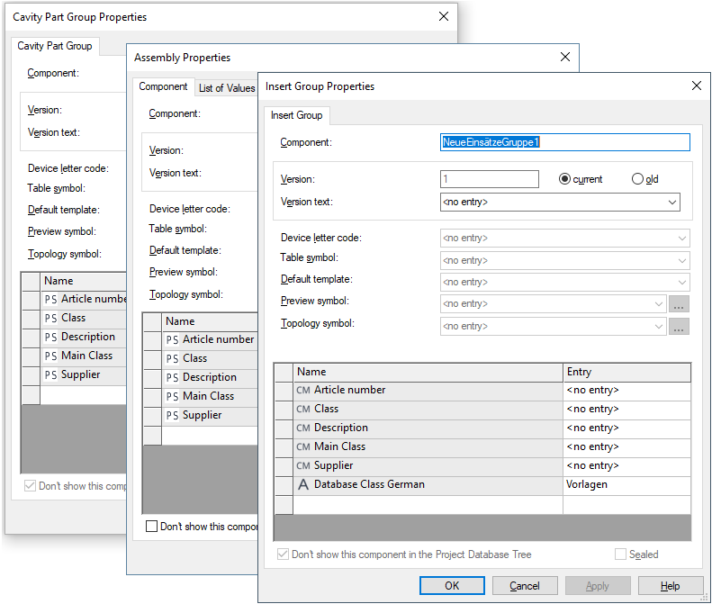
The bottom part of the dialog box contains the table for the specification of attributes.
To add additional attributes, select the empty Name field and left-click again to display a drop-down list box, displaying all of the available attributes for the selected component, from which a selection can be made.
Attributes that can be used only once and have already been associated with an assembly / cavity part group component, will not be displayed again in the list.
Select the Entry field to display a drop-down list box, containing all of the values that have already been used for that attribute within the project. If the required value does not exist, type in the new entry in the field.
Click on the Entry field containing a translatable text and press F3 to display the Translation Table dialog box. Individual columns can be sorted in ascending or descending order. Texts can be selected from the database.
Attention
The dialog box will not be displayed, if the entry field is editable (a field is editable, if the drop-down arrow is displayed at the right edge of the field).
|
Component / Cavity Part Group / Insert Group |
|||||
|---|---|---|---|---|---|
|
Component |
If the component has already been saved to the database, the name cannot be modified.
The Component name field cannot be empty.
The following characters are not allowed in E3.series as part of the Component name: , ; < > ' { } |
||||
|
Version |
If the component has already been saved to the database, the version cannot be modified.
The Version field cannot be empty. |
||||
|
Version text |
The Version description can always be changed.
The version status of the 'current' component in the database is instantly changed to 'old' when modifications have been made and confirmed using the Apply button. |
||||
|
Device letter code |
This letter code can be selected from the drop-down list or directly be defined. It can always be changed.
The Device letter code is the prefix character used to identify the component when it is placed in a drawing, e.g. 'M' for motor. |
||||
|
Table symbol |
This option is inactive with assembly / cavity part group components. |
||||
|
Default template |
Using this option, any default template symbol from the database can be assigned to the selected component.
The symbol is assigned the component and displays information on the component corresponding to the texts contained.
See also: Placing attribute template symbols |
||||
|
Preview symbol |
Preview symbols are displayed in the Preview window when selecting a component or device in the Database or Project tree view.
Any symbol can be selected from the selection list or using the
It's possible to define a special preview symbol for the following component types when editing in DBE mode:
Note
If this preview symbol shouldn't be visible in the project database tree, this can be defined by selecting the Don't show this symbol in Project Database Tree option when editing a symbol in the Database Editor.
See also: Defining Preview Symbols |
||||
|
Topology symbol |
This option is inactive and severs for information only.
Besides the possibility to define a neutral topology symbol for components or functional units with their corresponding components in the Settings in project, it's also possible to define a special topology symbol for each component in Database Editor using this option.
The drop-down list offers topology symbols for selection, or using the
Filter criteria can be defined therein.
See also: Topology - Overview |
||||
|
Name/Entry |
Two types of data are administered:
|
||||
|
Don't show this component in the Project Database Tree |
Check this option to mark the selected assembly / cavity part group as 'invisible' in order to prevent display of the assembly / cavity part group in the database tree of the project.
In database editor mode, this object is displayed as a gray icon in the database tree.
After terminating database editor these gray assemblies / cavity part groups are not any longer displayed. |
||||
|
Sealed |
If checked, the connector is predefined as 'sealed'. This ensures the function 'Wire Seal' works.
When inactive, the connector is predefined as 'not sealed'.
NoteThis setting can subsequently be changed in the project mode. |
||||