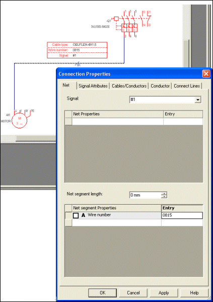
Visibility of Connection Attributes
A symbol can be used to display attribute values on a connect line. The advantage is, that the user can define various symbols to display different combinations of data and the symbol may contain any graphic.
The symbol can be placed on any position on a connect line (on orthogonal segments) and can also be placed several times on the same connect line. The symbol doesn't logically interrupt the connect line.
The attributes of the connect line can be changed by either editing them in the Connection Properties dialog or by simply changing the displayed values of the attribute on the symbol.
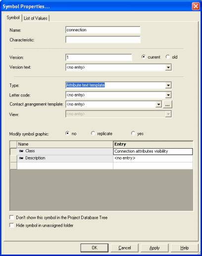
First of all, create a special template symbol that is to display the attributes on a connect line. Its symbol type is Attribute text template.
To do so, start the Database Editor and start Symbol creation by selecting:
-
the New Symbol command on the object menu by right-clicking on the header of the Component column in the Component View of the Database Window
-
or the New command on the object menu of a symbol by right-clicking on a symbol in the Symbol View or Misc View of the Database Window or by right-clicking on the column header.
A new working area (drawing sheet) named 'Symbol Type NewSymbol#' is created. Its size depends on the size defined in the Tools -> Settings -> Database Editor -> Symbol dialog box.
-
Right-click on the working sheet and select the Symbol Properties command from the displayed context menu, or right-click on the selected symbol in the tree view of the Database Editor window and select the Properties command from the displayed context menu.
The desired template type, i.e. Attribute text template, can now be selected from the Type drop-down menu.
The symbol can contain any graphics and text.
There are several predefined text types that are represented on this type of symbol and that display some predefined attributes of a connection.
Other text nodes can be added as well. As soon as an attribute is assigned to a text node (see Assigned Attributes in Edit Text Types), this attribute will be displayed at the text node position and can be changed with the text modification functions (see Text Properties).
Text type 410 is a user-defined text and text types 1003 - 1015 are system-generated text types.
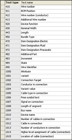
User-defined text type displaying the following:
-
Wire number
-
Conductor name(s)
-
Cable type(s) (Database entry)
-
Signal
-
Cable name(s)
-
Number of conductors
-
Higher level assignment(s)
-
Location(s)
The corresponding attribute is displayed on the defined symbol's text node, dependent on the attributes' assignment to the text nodes.

The symbol origin is placed on the connect line.
Assigning Attributes to Text Nodes
Using the Format -> Text Types... command in Database Editor mode the relation between the attribute and the text node can be defined.
Example
Text type 410 called 'Wire number' bears a relation to the attribute 'Wire number', which is assigned a 'net' or a 'net segment'.
A 'net' displays all connect lines electronically connected.
A 'net segment' displays a connect line from a connect point (e.g. a pin or a connection of another connect line) to the other connect point.

Text Type Definition
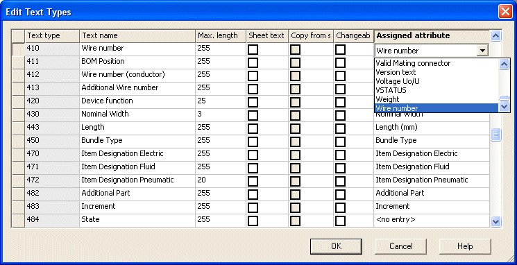
Attribute Definition

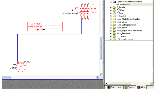
The attribute text template can now be dragged from the Database window onto the connect line. The connect line's attributes are displayed on the symbol's text nodes. If the text is modified the connect line's attributes are adjusted.
If the connect line's attributes are modified (Connection Properties) the text is automatically updated.
Dragging the attribute text template onto the connect line:
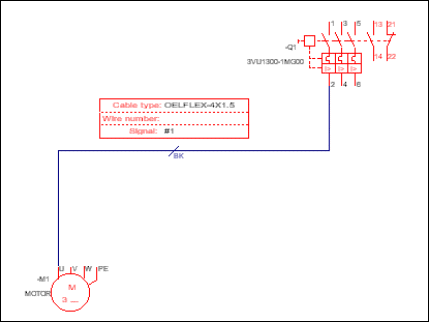
A cable is added to the connection by placing a conductor onto the connect line:
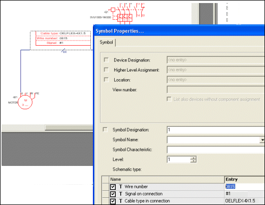
The wire number can be modified by editing the Symbol Properties:
Or by editing the Connection Properties:
