Text Properties - Text
To display/modify text properties,
-
left-click on the text and press hotkey F2 to begin editing the text, or
-
right-click on the text, select Text Properties... from the displayed context menu and select the Text view. To select more than one piece of text for modification, hold down the 'shift' key, then left-click on each piece of text and right-click on the final one to display the context menu.
-
Or left-click on the text to highlight it (or for multiple text, left-click on each piece of text while holding down the 'shift' key), select Format -> Text Properties... from the Main Menu bar and select the Text view.
-
Double left-click on the text.
The Text Properties dialog appears:
Text, such as device designation or a reference signal-text, can consist of only one line (no scroll bar is displayed on the right edge of the dialog box). Entry is completed by pressing the Enter key (or by clicking the OK button on the dialog box).
Line breaks:Line breaks, i.e. starting a new line with texts consisting of several lines can be done by pressing CTRL+Enter (a scroll bar is displayed on the right edge of the dialog box). It is completed by clicking on the OK button on the dialog box.
Note
If reference text is edited, the signal of the whole net will be changed.
It is not possible to change multiple signals.
|
Text |
|
|---|---|
|
Text type |
Displays the selected text type, which can be chosen from a drop down list. |
|
Source |
NoteThis list is only valid for following symbol types: (This list is deactivated for all other symbol types which are not allowed)
When an attribute with several owners is assigned to a placeholder, the desired owner can be selected in the selection list. Example can be found here. |
|
Text |
Displays information on the text type (unless text of different types has been selected), which can be chosen from a drop-down list.
The Text field is only displayed / active with variable texts. Texts such as Device Designation, Higher Level Assignment, Location, Component Code, etc., i.e. texts which need a text node to be defined but will be filled later on while working in project, cannot be defined/filled in DBE mode.
Existing text can be changed. This area is only active if one piece of text is selected. If more than one piece of text is selected, then only the font, level and visibility can be modified. |
|
Hotkeys F3/F5 |
F3: Select texts from translation database F5: Toggle between Edit and Preview mode
These hotkeys are only displayed, if text has been selected which can be modified. These hotkeys are not displayed with fix, unchangeable texts. They are only active, if entries have been made in the 'Description' column in the 'Language' database. If no Language database exists, this button is inactive.
The columns can be sorted in ascending or descending order. This allows for selection of text from the text database.
Required text is selected by:
Sorting of the text is controlled with Settings -> General -> Language. If only one language was selected in the settings, then only one language would be displayed in the Translation Table dialog. A modification of the language(s) or reloading the configuration data will update the graphic texts.
Multi-line symbol text is possible for translatable symbol text.
Multiple-line text from a Promis text database is converted using a script (^ becomes \r\n). It can be edited in the dialog box in Database Editor mode. To achieve a line break, you have to enter Ctrl+Ret.
See also Translation Table |
|
Separator |
A separator can be defined for attribute text template symbols, which is used when several identical attributes exist. This is particularly useful, for example, with conductors in connections.
Different wires, which are in a connection, can be displayed one under another.
When editing attribute text template symbols in the database, the separator can only be defined for the text types in the Text Properties using a string, which can also contain for example the special characters '\n' (i.e. line break) and '\t' (i.e. separated using tab key).
List of the text types that can be defined with a separator:
...as well as for all user-defined affiliated text types with attributes that have one of the following objects as an owner:
If no separator is defined on the symbol text, a comma is used.
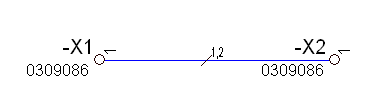
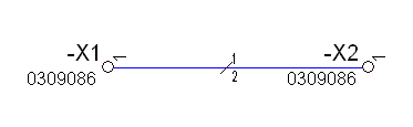
Example in Project ModeSeparated by a comma:
Separated using a line break:
|
|
Type of Hyperlink |
Select the desired type of hyperlink. The following types are available:
When changing the entry to <no entry>, the assigned hyperlink will be deleted for the selected text. |
|
Target |
The desired target, to which the hyperlink should point, can be selected from the selection list. |
|
|
Click on the push button to open the dialog from which the desired file can be selected.
This push button can only be selected if the type File was selected beforehand as the Type of Hyperlink. |
Effects |
|
|
Invisible |
Text can be defined as either visible or invisible by clicking in the checkbox.
Visibility can be changed for any texts. |
|
Lock position |
This option prevents text that is not assigned to a symbol from being moved.
When editing in DBE this option checked has functional effect, i.e. texts can be moved upon editing on the symbol or model sheet.
In the project, the option can be changed on placed symbols, independent of the database definition. When a symbol with such a text assigned is moved in project mode, the text is moved along with the symbol, but it cannot be separately be moved in relation to the symbol's origin.
When such texts are selected in addition to other objects, it is possible to move but those locked texts are ignored.
When displaying such locked texts, optical differences occur. When the texts are selected, the left lower handle is represented by a key icon.
Example
|
|
For text nodes it is possible to define whether multi-line texts shall be displayed as single-line.
When outputting, all line breaks in the text are replaced by a blank space.
This applies to multi-line symbol and model texts. |
|
|
Reset text box |
It is possible to define a text box at texts, that represents the max. width/height of the text.
This text box is represented as a rectangle, that will then contain the text. A line break of the texts takes place automatically.
This box is defined by modifying the text handles (e.g. increase/decrease in size, etc.).
To delete such a text box, this option must be checked. This option is only active, when a box is already defined.
Notes
|
|
Pictogram |
When checked, the translatable passage is displayed as pictogram, if defined.
|
|
Linear measure without unit |
When checked, the length unit at texts with length specification is suppressed.
NoteIt is only checked, when the text displays an attribute of the type 'linear measure'. |
|
Level |
Defines the drawing level on which the text will be placed.
Can be applied to all texts (symbol, graphic and dimension). |
|
Position
|
The position (X-position; Y-position) of the text is displayed on the sheet (as offset from the original symbol) by use of two text fields. |
Ballooning |
|
|
Arc/Oval/Rectangle/Ellipse |
All texts, except for fix symbol texts, can be defined as ballooning texts.
The ballooning text can be displayed within
|
|
Display subsidiary line to owner |
This option defines whether a subsidiary line is to be displayed to the owner.
The following applies:
|
|
Line |
A Line will be inserted on the top/in the cent |
|
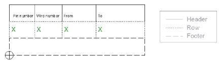
This option is only available when editing text of symbols of type ' Table'.
Table text must be assigned to the table's header, row or footer.
NoteWhen placing the following text types:
they are automatically assigned the Table elementRow. Example
(See also: Formboard) |
|
|
Specifies the side in terminal plan |
This option is only displayed when editing terminal plan text types.
Text marked with (*) can exist on the internal as well as on the external side of the terminal plan.
This applies to all text types of a terminal plan sheet or of a terminal plan row, which have an attribute assigned. |
|
Internal/External |
Specifies on which side of the terminal plan sheet/terminal plan row the text type is to be defined. |