Defining Components
What is a component?
Components are physically available units.
A device is a component that is marked with an item designation.
Components are saved to the database and contain
-
as well as a model for display on the circuit board and its physical description.
E3.series manages all elements of a device automatically.
Further information can be defined for components such as code number, descriptions, manufacturer, price and much more.
Components consisting of ONE symbol (Standard Devices and Terminals)
Upon going through the Component Wizard's steps to create the new component, select the Edit component graphically command in the last tab of the Wizard, the Complete tab.
The new working area (drawing sheet) will be created. Its size depends on the size defined in the Tools -> Settings -> Database Editor -> Component dialog box.
All symbols that will be part of the component, can now be placed on the sheet.
The grid display can be activated using View -> Rulers and/or Grid and modified using Tools -> Settings -> Database Editor -> Component.
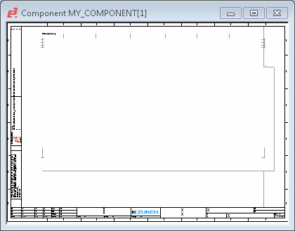
To create a component consisting of one symbol only, proceed as follows:
-
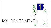
Drag&Drop the desired symbol from the Component or Symbol view, of the Database Window into the working area.
-
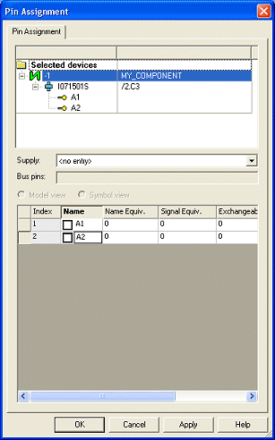
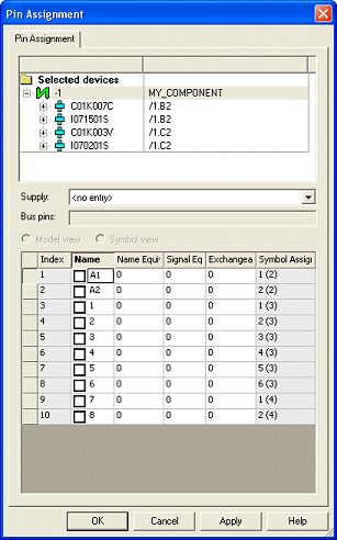
Define the pin names of the symbol by means of the Pin Assignment... command on the symbol object menu (or the Edit menu on the Main Menu bar). For terminals, the pin name is $.
-
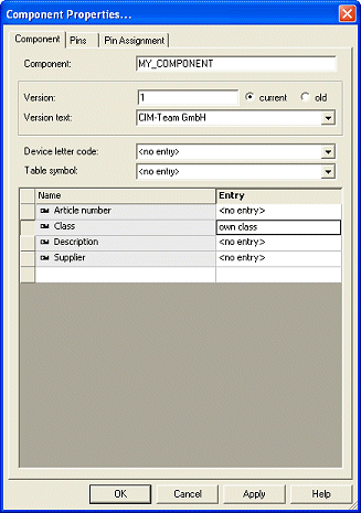
The following definitions are displayed, and most can be defined/modified, in the Component tab of the Component Properties dialog box:
-
Version
-
Current/old
-
Version text
-
Device letter code
-
Table symbol
-
Attributes
-
-
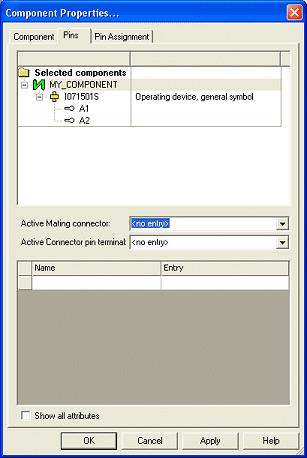
The following definitions are made in the Pins View of the Component Properties:
-
Active Mating connector
-
Active Connector pin terminal
-
Finally, the component can be saved to the database by means of the Save to Database command on the component object menu or the File menu on the Main Menu bar.
Components consisting of SEVERAL symbols (Master/Slave relations)
Upon going through the Component Wizard's steps to create the new component, select the Edit component graphically command in the last tab of the Wizard, the Complete tab.
The new working area (drawing sheet) will be created. Its size depends on the size defined in the Tools -> Settings -> Database Editor -> Component dialog box.
All symbols that will be part of the component, can now be placed on the sheet.
The grid display can be activated using View -> Rulers and/or Grid and modified using Tools -> Settings -> Database Editor -> Component.

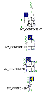
To create a component consisting of several symbols, proceed as follows:
-
Drag&Drop the desired symbols from the Component or Symbol view of the Database Window into the working area,
-
Definition of Symbol Order for Components
The following modes are available for defining the symbol order:
- Reorder mode
- Insert mode
- Swap mode
To define the symbol order
- select the command Tools -> Start Database Editor in the main menu
- open a 'normal component' with several symbols in the database editor
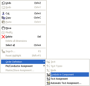
- click on the command Edit -> Order Definition -> Symbols in Component in the main menu, or
- click on the Symbol Order
 icon in the Database Component toolbar
 - the Symbol Order Definition dialog opens
Reorder mode: The symbols are reordered. With Next click is number: it's possible to specify a starting value that is automatically increased by one with each click on a symbol. Press <Esc> to abort the command.
Swap mode: The symbol with the number specified in Next click is number: is exchanged with the symbol on which you click.
Insert mode: The symbol with the number specified in Next click is number: is placed at the position on which you click. Subsequent symbols are moved back (renumbered).
The new order is displayed in the blue text fields next to the symbols.
Please note, that the first symbol is displayed in the preview window when selecting the component within the tree structure view.

-
Next, define the pin names by means of the Pin Assignment... command on the symbol object menu (or the Edit menu on the Main Menu bar).
-
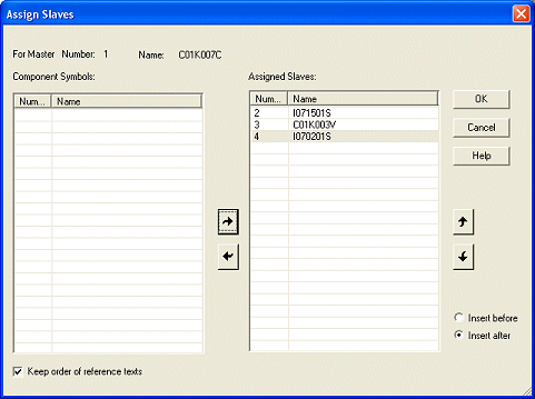
Use the Master/Slave Assignment... command in the symbol's context menu (or the Edit menu on the Main Menu bar) to define the Master/Slave relationship.
This will display the Assign Slaves dialog box where you can select the Slave(s) for the specific symbol and the order in which they appear. Master/Slave relationships are used to define the cross-referencing of component symbols.
Typically there is one master symbol which displays the cross-references to all the slave symbols. However, it is also possible to define multiple Master/Slave relationships so that cross-references to other symbols of a component can be assigned to more than one 'master' symbol.
Finally, the new component can be saved to the database by means of the Save to Database command from the object menu or the File menu on the Main Menu bar.
Adding a model to the component
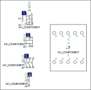
Upon placing several symbols on the component sheet, it is possible to add a model to the new component.
To add a model, proceed as follows:
-
Drag&Drop the desired symbols and the model from the Symbol and Model view of the Database Window into the working area.
-
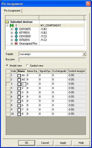
Next, define the model's pin names by means of the Pin Assignment... command on the context menu (or the Edit menu on the Main Menu bar). Check the Model view for pin assignment.
-
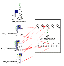
To define the schema pins to the corresponding model pins select Edit -> Pin/Conductor Assignment -> Schema/Model or click on the Pin Assignment Symbol/Model button
 from the Database Component toolbar.
The schematic symbol pins can then be assigned to their model pins by simply clicking on them. However, these options are available, when the command is active, by right-clicking to display the context menu.
To display the logic lines (subsidiary lines) between the assigned schema/model pins, use the command Tools -> Settings... -> Database Editor -> Display -> Subsidiary Lines: Between assigned schema and model pins. Alternatively click on the Schematic/Model Pin Assignment Subsidiary Lines button ![]() .
.
Finally, the new component can be saved to the database by means of the Save to Database command from the object menu or the File menu on the Main Menu bar.