
Re-transferring Routed Terminal Ports from Model to Schematic
After routing, the terminal's schematic symbol displays, which connection is connected to which terminal port.
Defining Terminal Ports in Database Editor
When editing a terminal in Database Editor mode, it is possible to define a terminal port name for each pin using the Port column in the Pin Assignment dialog on the component pin.
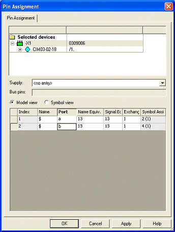
The terminal port name describes the physical pins of the model.
Displaying on Symbol
The following text types are available for displaying the pin and port names:
-
#1094 - Port name
-
Displays the terminal port name in the schematic.
-
-
#1095 - Port name from panel
-
Displays the terminal port name re-transferred from panel to the schematic.
-
-
#1096 - Pin and port name
-
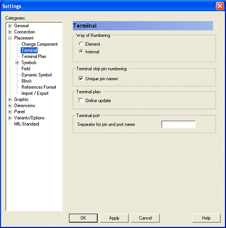
Displays both the pin and port name separated by a definable separator (<pin><separator><port>). The separator can be specified in the project's Settings -> Placement -> Terminal -> Terminal port using the Separator for pin and port name option. By default, no separator is defined.
-
Interface Display and Display of Conductors/Wires
In trees, tooltips and dialogs, the pin name is displayed in the format <pin><separator><port>.
When a connection was routed on a terminal in the panel, it is not mandatory that the routed panel pin matches the graphic conductor routing in the schematic.
The connect line ends correspond to the panel wire ends (e.g. <DevDes1>:<pin1><sep><port1> -> <DevDes2>:<pin2><sep><port2> ).
Functionality for Re-Transferring routed Ports from Model to Schematic
When a connection is routed in the panel, it is possible to re-transfer the connect line ends to the schematic. The following text type is available therefore:
This text type displays the terminal port name of a connect line end from panel in the schematic at the corresponding text that contains the graphic connection in the schematic. What is more, the panel terminal port name is displayed in the connection target text.
In some cases the user wants to predefine the terminal port to be auto-connected in Panel. These predefined terminal ports must be used for routing in the panel afterwards, also in case of a longer routing path.
It is therefore possible to edit the terminal port text in the schematic, as long as no wire is routed in the Panel. I.e. it is possible to already predefine in the schematics to which terminal port is routed in the panel.The system recognizes which texts were manually entered, so these automatically remain existing, when the wire path is removed from the panel, and the next 'Autoconnect' creates the connection to this terminal port again.
To edit the terminal port text (i.e. texts of the type Port name from panel (#1095)) in the schematic, check the option Use manually defined ports for terminals in schematic under Tools -> Settings -> Panel -> Connection.
Port Names in Terminal Plan
To display the terminal port name of a routed wire's pin in the terminal plan, the following terminal plan row symbol text types are available:
-
#1101 - Port name of terminal pin at internal side
-
#1102 - Port name of terminal pin at external side
-
#1103 - Port name (ext.)
-
#1104 - Pin and port name (ext.)
-
#1105 - Port name (int.)
-
#1106 - Pin and port name (int.)
The terminal port name of a routed wire's pin in the terminal plan is output.
When the wire is not routed in the panel but exists in the schematic, the terminal port where the wire is routed, is output.
When no wire exists, the terminal port of the pin is output, where the graphic connection is placed.