Autoconnect in Panel
The panel functionality is only available when a E3.panel license is present!
Automatically connecting in the panel
The Insert -> Autoconnect command from the main menu bar offers the following option forE3.panel:
-
Panel Autoconnect

Depending on the selection, the following items will be routed in the panel:
-
right-click an individual device and select the Panel Autoconnect command from the displayed context menu to wire all the connections on that device to all its destination components
-
select several devices and select the Panel Autoconnect command from the displayed context menu to wire all the connections to these devices and their destination components
-
right-click an individual connect node of a device and select the Panel Autoconnect command from the displayed context menu to wire all connections that have the same signal.
Note
Connections without signals are not routed with this function.
Thus, connections without signals but with
The properties of the wire used for the connection, in addition to the graphical representation, are defined by the Used Wire Type option in the Tools->Settings->Panel->Connection dialog.
It is possible to abort the Insert -> Autoconnect -> Panel Autoconnect using the Esc key. This is useful when activating the command in large projects for the whole layout.
Moreover, the status of the command is shown by a progress bar in the status line.
The restriction attribute can bear several attribute values on the cable duct as well as on the connection and/or signal. The system then searches a common value. If this value does not exist, the duct will be ignored.
Example
If the signal #1 bears the attribute signal class A, signal #2 bears the attribute signal class B and the cable duct bears the signal class A and B, the wire can be routed in this cable duct.
Connections through wires/cables
The following applies for connections through wires and cables:
-
Graphical connections (single pin display with signal) are routed through a wire in Panel (by means of the Autoconnect command).
-
Graphically connected pin groups are not routed.
-
If connector pins are already connected with conductors/wires, these connection elements are routed.
Determination of the routing path
The Panel Autoconnect command recognizes the type of cable duct and determines the routing path as follows:
-
Coordinate of the first connection point
-
Center above the cable duct at the first connection point's level
-
Vertical to the first connection point's level on the lower edge of the cable duct
-
Center of the lower edge of the cable ducts
-
Vertical to the final connection point's level
-
Center above the cable duct at the final connection point's level
-
Coordinate of the final connection point
Notes on the routing path
One end of the wiring path can consist of a cable duct wiring and the other end of a backplane wiring.
However, it is not possible that a cable-duct wiring is created on both ends and a backplane wiring between the ends.
Display of the wiring path in the backplane can be switched off using the View -> Connection Types command (or the appropriate toolbar icon). Only the wiring path in normal cable ducts is then displayed.
Calculation of the routing path for backplane connections
For the calculation of the routing path, a cable duct is starting from both ends (as for the preferred direction). From these points, a direct connection is taken. As it is a backplane wiring, the Z coordinates have to be set accordingly.
When routing wires without cable duct the Z coordinate of the pin is kept for all deviating points.
As the wires do not run at the lower edge of the cable duct, but further behind (for example behind a fitting panel), this depth is added twice for the calculation of the wire length. This supplement can be defined by means of the Backplane Connection Distance option in the Settings....
As wires of the X wiring are either laid via wire combs or through punched strips, the wire pathway depends on these elements. This means, if two wire combs are found for a wire, an X wiring is generated. However, there are also cases, where wiring in the panel is carried out through an X wiring, whereas wiring in the door is realized by means of a duct wiring. Part of a wire can thus be an X wiring and the other part a duct wiring.
If routing fails, the following are possible reasons:
-
During routing, the cross-section of the wire is checked against the max./min. cross-sections allowed at the connect points. Moreover, the system also checks the maximum number of wires at connect points as well as the maximum total cross-section.
-
If wire and cable duct possess the same attribute, but with different values, the wire is not routed in the cable duct.
-
The checkbox 'Blocked' in the Device Properties dialog for a cable duct can be activated to prevent any wire from being routed in that duct.
-
The fill level of a cable duct is displayed as graphical information for the user. If the duct is full, you can either increase the size of the cable duct in the Device Properties dialog or decrease the size of the wires you wish to route in the duct.
Example for routing classes
Routing classes offer the possibility to control the routing paths when using Autoconnect in panel.
The definition for E3.series is based on internally defined attributes of all devices and connection types. The following example is to demonstrate the operation mode:
-
Three cable ducts and a conductor to be automatically routed are available.
-
The three cable ducts are placed U-shaped.
-
To control the routing path the attribute 'ConnectionClass' is defined.
-
The cable ducts are assigned different attribute values. The left cable duct is assigned the attribute value 'ConnectionClass == A', the right one is assigned 'ConnectionClass == B'. The upper cable duct is not assigned any attribute.
-
The conductor to be routed is assigned the attribute value 'ConnectionClass == B'.
-
E3.series is routing these conductors starting at the upper cable duct through the right cable duct to the end point.
-
The following rules apply:
-
A conductor/cable without attribute can be freely routed.
-
If an attribute is predefined, the routing path has to bear the same attribute.
In the example, the conductor with attribute 'B' can only be routed through the cable duct bearing attribute 'B'. The cable duct with the attribute 'A' is locked as routing path.
-
A cable duct without attribute definition can bear all conductors/cables independent of their attribute value.
In the example this applies to the upper cable duct.
-
A cable duct can also bear several attribute values.
In the example, a cable duct can be assigned the attribute value 'ConnectionClass == A,B'. This cable duct can bear conductors with attribute 'A' or 'B'.
-
E3.series verifies all assigned attributes of the affected devices, independent of their names.
Mechanical Jumpers as a Special Wire in Panel
The attribute Jumper for terminal, with which wires in the schematic can be designated as jumpers in the terminal plan, is interpreted in panel when automatically routing:
-
If a wire contains this attribute (arbitrary value), the "wire" is not connected any longer using cable ducts but it is connected as a direct connection from pin to pin.
-
This explicitly applies for cases in which for example two terminals, that have jumpers like this, are placed on different mounts. The user either has to systematically delete the attribute (a wire will then be connected in the ducts) or to replace the terminals.
For the user it is easy to control the interpretation of the wire as a mechanical jumper e.g. using the WireType of the wire. The recognition of such wires is also easy: the attribute Jumper for terminal is either available or not.
Note
If the attribute is added, changed or deleted on an already existing conductor/cable a reconnect will be executed, which means the wire will be connected in cable ducts again or it will be connected directly.
Using the 'Jumper for terminal' attribute when automatically connecting in the panel
The jumpers that are defined in Settings -> Conductors/Wires -> Used Jumper Type are used for automatic connection in the panel, if no appropriate jumper is defined on the signal.
The following criteria are required for autoconnect:
-
Both pins are jumper pins
-
If the pins belong to the same jumper, it is possible to connect between different jumper levels, otherwise the levels must be the same
-
Only same devices can be placed on a mounting rail
When manually connecting within the panel, jumpers are selected according to the criteria mentioned above.
See also: 'Jumper for terminal' attribute for model pins
Considering restrictions when searching for entry cable ducts
When searching for the wire entry cable duct starting at the pin the restrictions for wires are taken into consideration.
When executing the Autoconnect command the Restrictions against all as well as the Restrictions for connections for the wire part from the pin to the cable duct are verified.
In case collisions occur, i.e. a wire part would run through such a restriction, this wire direction will be rejected and, if possible, an alternative direction will be taken.
Highlighting connected cable ducts
Routing problems coming from cable ducts not being connected can easily be determined and solved using the commands Highlight directly connected cable ducts and Highlight all connected cable ducts.
Highlighting connected cable ducts can be done from panel sheets, from within the tree view and the Device table.
Highlight color is defined under General -> Highlight -> Color.
Pairs of cable ducts defined as inlet and outlet, are considered as one single cable duct.
Note
When the selected cable duct or one of the connected cable ducts has variant positions assigned and all variants/options are simultaneously active, the output may contain erroneous information.
To highlight cable ducts connected to a certain cable duct, right-click on the desired cable duct on a panel sheet, in the tree view Panel - Placed or in the Device table.
Select the command Highlight directly connected cable ducts from the displayed context menu to highlight the cable ducts that are directly connected to the selected cable duct.
Or select the command Highlight all connected cable ducts from the displayed context menu to highlight the cable ducts directly or recursively connected to the selected cable duct.
When the cable duct is placed on several sheets, the Output window's Results tab shows all sheets including a link to the corresponding sheet on which the cable duct is placed:
When connected cable ducts are placed on sheets that are not opened, the corresponding sheet are opened and all connected cable ducts are focussed and highlighted.
Regarding cable ducts placed on shared sheets or 2D view sheets, restrictions exist.
Cable ducts placed on shared sheets are highlighted but not focussed. The corresponding shared sheet is not additionally opened.
Cable ducts placed on 2D view sheets are highlighted and focussed, only if the corresponding sheet was created using Create 2D View....
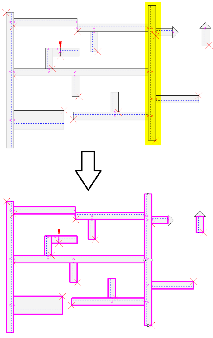
Example: Show all cable ducts that are directly connected to the selected cable duct
The command Highlight directly connected cable ducts is executed for the cable duct highlighted in yellow.
All cable ducts directly connected to the highlighted cable duct are highlighted in purple and focussed:
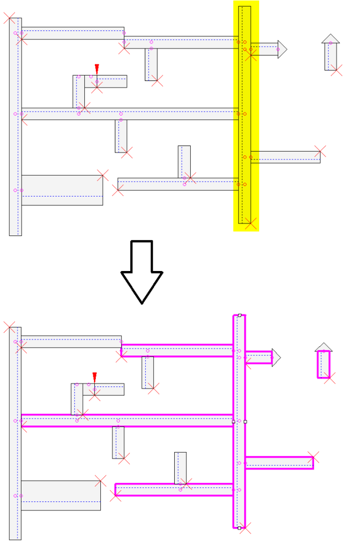
Example: Show all cable ducts that are directly or recursively connected to the selected cable duct
The command Highlight all connected cable ducts is executed for the cable duct highlighted in yellow.
All cable ducts that are connected directly or recursively via a directly connected cable duct, are highlighted: