
Create 2D-View of a Model
The panel functionality is only available when a E3.panel license is present!
Creating 2D View of Pivoted Model
To move, delete, or place models in closed (folded) panels, it's possible (and may also be required) to generate a 2D view of the rotated part(s).
Therefore, right-click on the desired model
-
in the 2D view
-
in the 3D view, or
-
in the tree view
and select the Create 2D View... command in the displayed context menu.
Note
At least one slot of the type Point, Line, or Area must exist in order to create a 2D view of a model.
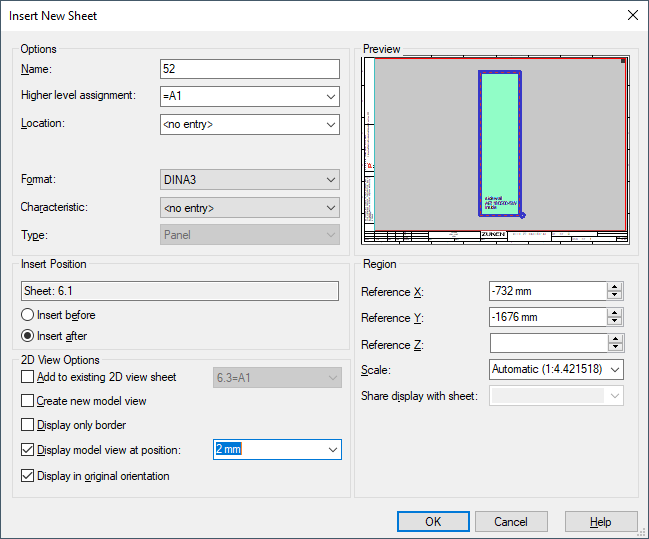
The Insert New Sheet dialog automatically opens, in which the desired name, sheet format and characteristic of the new sheet can be specified for the view to be generated:
Note
The values Position X and Position Y define the distance between the sheet's origin and the model's origin.
Negative values mean that the sheet's origin is positioned to the left of or below the model's origin. Positive values mean that the sheet's origin is positioned to the right of or above the sheet's origin.
The sheet type Panel is activated by default.
Afterwards, the first created sheet is displayed in the Sheet tree view by a special icon  . Additionally, panel sheets are also displayed by a special icon in the Sheet tree view:
  .
.
See example:
This "2D view sheet" can now be edited like normal. Commands for pivoting and rotating refer to the coordinate system currently visible (not to the 'world'). Even though only a part of the whole is displayed in this 2D view, a 3D collision check is carried out for models that cannot be seen.
Note
The side wall or the component, for which a 2D view was created, is not displayed on the base sheet as long as the 2D view exists and then only displayed again if the "2D view sheet" is deleted in the tree view. Models, of which a 2D view was created, are displayed in the 3D view.
The blue border around the base sheet identifies it as the "2D view sheet".
When a 2D view is open, the status bar shows the distance between the model's origin and the mouse cursor and the sheet coordinates on which the mouse cursor is located.
The model's origin and its coordinates remain. The values of the sheet coordinates are relative to the model's origin.
Negative values mean that the mouse cursor is located to the left or below the model's origin. Positive values mean that the mouse cursor is to the right or above the model's origin.
Create 2D View on existing 2D View Sheet
Therefore, right-click on the desired model in the 2D view and select the Create 2D View... command in the displayed context menu.
The Insert New Sheet dialog automatically opens:
Click the check box Add to existing 2D view sheet within the area of 2D View Options.
-
The check box can only be activated when a sheet with 2D view is already existing. If this check box is inactive or no 2D view is existing, a new 2D view sheet will be created.
-
When this check box is active, an already existing 2D view sheet can be selected in the list to add the new 2D view.
Following options are available with the check box Create new model view:
-
The model will be displayed on the former sheet (where the model is placed) as well as on the new 2D view sheet when the check box is active.
-
The model will be moved to the 2D view sheet when the check box is inactive.
Following options are available with the check box Display only border:
-
When this option is checked, the system creates a 2D view of the region border only. The contours of restricted areas, cutouts or drill holes are not visible in the 2D view.
-
When this option is not checked, the system creates a 2D view of the complete region including all contours.
Using the option Display in background the model of which the view was created is displayed in the background. Symbol graphics are thus optically not hidden by their assigned owner model.
Note
When the option Display only border is activated, Display in background is automatically checked.
Note
When importing panel sheets, the system tries to merge models with 2D views.
The following is valid:
-
Only one 2D view per model
-
Models and 2D views may not differ regarding the following points:
-
Position
-
Length (mounts, cable ducts)
-
Rotation/Tilting
-
When importing, panel sheets are no longer moved to a new position. This is valid for all imported panel sheets (not only 2D views).
Exceptions
-
If models/2D views collide and they cannot be inserted at the respective position
-
By executing the command Paste Extended, the subcircuit sheets are moved to a new position.
Already Placed 2D Views Can Be Deleted
If there are several 2D views on a 2D view sheet, the 2D view can be deleted using the new context menu command Delete 2D View.
How to delete a 2D view on the 2D view sheet
-
right-click on the 2D view and select the command within the displayed context menu Delete 2D View,
-
the 2D view is deleted on the 2D view sheet
Jump to 2D View
From a model context menu it's possible to jump to a 2D view if a 2D view of the model has been created.
This enables to determine rather quickly, for example, whether a 2D view of the selected model has already been created, and to jump directly to the 2D view for further editing of the model.
To jump to a 2D view of a model, open a panel sheet, on which the model is placed. Right-click on the model to open the context menu.
Select Jump -> Jump to 2D View.
Note
If Jump to 2D View is not listed in the context menu, a 2D view of the model hasn't been created yet. In this case, first select Create 2D View in the context menu. The Insert New Sheet window opens. Activate Create new model view under 2D View Options.
Create 2D Views of Selected Mounting Sides
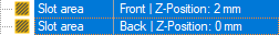
To display the mounting side of a model in 2D view, select the slots of two opposite sides in the Device tree.
Either slots from Front and Back, slots from Left and Right or slots from Top and Bottom:
Right-click on the selection, open the sub-menu Create 2D view from the displayed context menu and select the side of which the view is to be generated.
The displayed mounting side results from the positions of the selected slots and the direction of the view created.
The following table summari
|
Mounting side |
Position of the selected slots |
Direction of the view to be created |
|---|---|---|
|
Inside left |
Left and Right |
Right |
|
Outside left |
Left |
|
|
Inside right |
Left |
|
|
Outside right |
Right |
|
|
Inside front |
Front and Back |
Back |
|
Outside front |
Front |
|
|
Inside back |
Front |
|
|
Outside back |
Back |
|
|
Inside top |
Top and Bottom |
Bottom |
|
Outside top |
Top |
|
|
Inside bottom |
Top |
|
|
Outside bottom |
Bottom |
Consider Slots' Penetration Depth in 2D Views
To take into account the penetration depth of slots in 2D views, right-click on a model in the Device tree or on the sheet.
elect the Create 2D view command from the displayed context menu. If several views can be created for the model, select the respective direction from the sub-menu.
The Insert New Sheet dialog appears.
Define the properties of the 2D view sheet to be created, activate the option Display model view at position: and specify the penetration depth in the model.
The Preview displays which slots are visible with the defined penetration depth:
Note
This option is available only if Display only border is activated and the model contains slots of the direction for which the 2D view is created.
Confirm with OK.
The model's 2D view is created with the defined penetration depth.
The option and penetration depth can also be changed in the Sheet Properties.
Display Rotated Models in Original Orientation
To create 2D views of model with their original orientation, right-click on a model in the Device tree or on the sheet and select the Create 2D view command from the displayed context menu. When several views can be created for the model, select the desired direction in the sub-menu.
The Insert New Sheet dialog appears.
Define the properties of the 2D view sheet to be created and activate the option Display in original orientation.
The Preview shows the original orientation of the model:

Note
If only 2D views were created with the option Display in original orientation, models from which 2D views were created can be rotated and tilted as desired.
If the 2D views were created without the option, the displayed models can only be rotated around the Z axis of the model. The representation of the model on the 2D view is updated accordingly.
Project Panel Sheets on 2D Sheets
Panel sheets can be displayed as 2D orthographic projection. Models are represented as solids in the projection.
This makes it possible to clearly display in 2D especially those models that have been rotated on multiple axes and pivoted prior to placement.
Note
Among others, the following objects cannot be currently displayed in 3D and on the 2D projection, or only to a limited extent:
-
dimensions
-
text objects
-
fields
-
free graphics
-
fill degree of cable ducts
There are two ways to create the 2D projection of panel sheets:
-
Open a panel sheet and select the command Projection on 2D sheet
 in the Panel toolbar:
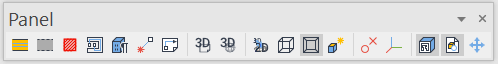
-
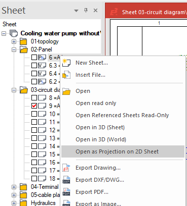
Open the context menu of a panel sheet that is not open in the sheet tree and select the command Open as Projection on 2D Sheet:
The activated display modes and associated options are highlighted in the toolbar with a dark gr