Pin Table
To quickly and easily edit pins also in larger projects, the Pin Table is available.
Displaying the Pin Table
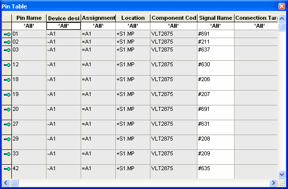
After having selected the View -> Pin Table command from the Main menu bar, a window appears displaying an Excel-like table listing all pins contained in the project with their signals, connection targets and other information (e.g. connected cables).

The columns contain the following predefined information:
-
Pin name
-
Device designation
-
Assignment
-
Location
-
Component code
-
Signal name
-
Connection target
-
All attributes with the corresponding owner Component pin, Device pin, Block pin or Connector pin, can also be defined as column (See also: Displaying attributes in additional columns)
'Jump to' Panel, Schematics and Project Tree
The 'Jump to' functionality allows to quickly and easily switch to objects that are already placed in the drawing. It's possible to directly jump into the Pin Table or from the Pin Table to the desired pin on the sheet or in the Project tree.

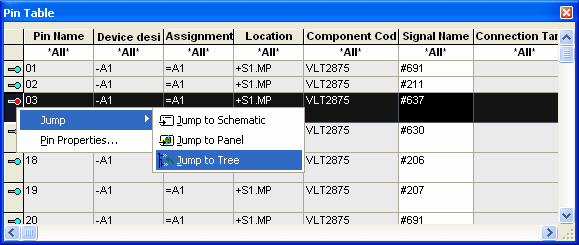
Right-click on the line with the desired pin and select the Jump to Schematicor Jump to Panelcommand from the displayed context menu to open the sheet where the desired pin is placed on.
To activate the pin in the Project window select the Jump to Tree command.
To directly jump from a pin to the Pin Table
-
right-click on the desired pin in the Device or Panel tree and select the Jump to Device Table command from the displayed context menu, or
-
right-click on the desired pin in the drawing and select the Jump to -> Jump to Pin Table command from the displayed context menu.
The Jump to Pin Table command opens the Pin Table, if not yet displayed, with corresponding row being open and active.
New Connection by Dragging&Dropping Pin from the pin Table to the Connection Table
By dragging & dropping a pin from the Pin Table or the Database tree view onto the Connection Table, a new connection can be created. To drag a pin onto the Connection Table, select the entire row, move the cursor until a gray rectangle appears
See example:

Drag the row to the desired position in the Connection Table.
A new row is temporarily created in the Connection Table. In case no target pin is dragged onto the Connection Table, the newly added row is deleted after closing and reopening the table.
A target pin is dragged&dropped from the pin table to the 'To Device' or 'To Pin' row of the new line in connection table.
After inserting a target pin, a connection is automatically generated between the two pins using the wire defined under the Used Wire Type section of Settings -> Connection -> Wires/Conductors. This wire receives no cross-section check.
Connection targets in the Pin Table are merely used for information and cannot be changed.
An existing connection can be disconnected by dragging a new pin from the Pin Table onto an existing pin in the Connection Table. Thus the new pin is swapped for the existing pin.
Note
To generate a new row, "drop" the desired object underneath the last row in the Connection Table using Drag&Drop.