
Export DWG/DXF
To export a sheet or part of a sheet as DWG/DXF file,
-
select the File -> Export -> DXF/DWG... command from the Main Menu bar and
-
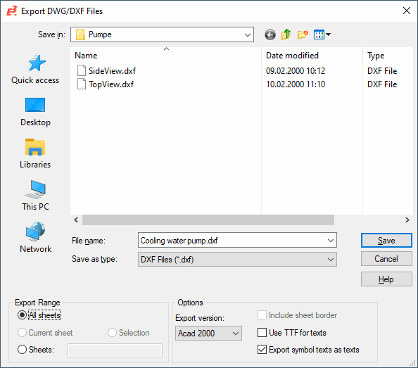
complete the following dialog box:
The system always starts the dialog in the directory defined in the Settings' Default Directory page.
Text and attributes of a symbol are output as attributes. Texts are visible attributes. This allows processing the DWG/DXF file.
Note
-
It is possible to export opaque texts in DXF format only with activated Use TTF for texts option.
-
When outputting texts as attributes using DXF export, only a block with a symbol name will be output instead of blocks with symbol names and attached consecutive numbers. Furthermore, the attribute query texts are output without a text copy number.
-
To use the ASCII codepage instead of DOS850 in the DXF file, the registry value 1 must be defined under HCU\Software\Zuken\E3.series\<version>\Settings "DXFDWGCodepage"
-
When exporting in DXF format, the level names are used when assigning the DXF layers to the E3 levels, in case no assignment is defined in the configuration file (DXFExport.cfg and DXFImport.cfg). Therefore, the level names must not contain invalid characters (<>/\":;?*|,=`).
-
Upon opening exported DWG/DXF files in AutoCAD objects containing white areas may be displayed in black, if the background color in AutoCAD is white. AutoCAD automatically converts colors of areas to complementary colors (in this case black). When switching AutoCAD's background color to black, the areas appear in white.
-
The installation directory of E3.series contains a template of the configuration file DXFExport.cfg that can be used for the export.
When a configuration file is used when exporting, a corresponding message is displayed.
When exporting DWG/DXF files, the Output Window shows which configuration file used.
|
Export DWG/DXF Files |
|||||||||||||||||||||
|---|---|---|---|---|---|---|---|---|---|---|---|---|---|---|---|---|---|---|---|---|---|
|
Save in |
Allows you to select drive and folder where you want to save the file. |
||||||||||||||||||||
|
File name |
Enter a name for the file in File name. |
||||||||||||||||||||
|
Save as type |
The default extension is *.dxf. |
||||||||||||||||||||
|
Save / Cancel |
Click Save to export the data or Cancel to cancel the operation. |
||||||||||||||||||||
|
All sheets |
Check this option to export all sheets. For All sheets, the Include sheet border checkbox is inactive. |
||||||||||||||||||||
|
Current sheet |
Select this option to export the current sheet. For Current sheet, the Include sheet border checkbox is inactive. |
||||||||||||||||||||
|
Sheets |
Check this option to export one or several sheets. Define the sheet name(s) of the respective sheet(s); these must be separated by semicolon. When the Export DWG/DXF... command is selected through the context menu activated on a folder, sheet or several sheets in the Sheet tree view, the system automatically enters the corresponding sheet names. For Sheets, the Include sheet border checkbox is inactive. |
||||||||||||||||||||
|
Selection |
Use this option to export one or several elements. The Selection option is only active if one or more elements are selected on the current sheet. For Selection, the Include sheet border checkbox is active. |
||||||||||||||||||||
|
Options |
Select the Autocad version to be used for creation of the file. The following versions are supported:
|
||||||||||||||||||||
|
Include sheet border |
This option determines whether the selected drawing / part of the drawing is to be saved along with its corresponding sheet texts and sheet formats. Only for Selection is this option active. |
||||||||||||||||||||
|
Use TTF for texts |
This option determines whether the selected drawing / part of the drawing is to be used as TTF (True Type Font) for texts. |
||||||||||||||||||||
|
Export symbol texts as texts |
This option determines whether symbol texts are to be exported as texts.
NoteIf this option is unchecked, symbol texts are exported as the symbol's attributes. |
||||||||||||||||||||
Configuration File for DWG/DXF Export
Using a configuration file, DWG/DXF export can be specified. For example, it is possible to assign levels of E3.series to layer names in DXF/DWG files using an assignment table. Thus, colors and line types can also be assigned.
This can be defined in the DXFExport.cfg assignment file of the installation directory:
|
Key |
Format |
Description |
|---|---|---|
|
[Levels] |
<Level in E3.series>=<Layer name of AUTOCAD>
Example: 1=ONE 3=THREE 12=TWELVE |
A particular AUTOCAD layer can be assigned a E3.series level. Any name is possible as AUTOCAD name as these layers are generated instead of the standard.
When no name is defined for the layer, the name of the dialog Levels is used.
By default, the layers are named LAYER1 to LAYER256. |
|
[Linetypes] |
<Line type in E3.series>=<Line type of AUTOCAD>
Example: 1=CONTINUOUS 2=DOT 3=DASHDOT 4=DASHED 5=DASHDOTX2 6=CENTER 7=PHANTOM |
A particular AUTOCAD line type can be assigned a E3.series line type. This is not necessary for default line types.
The following default line types are available. CONTINUOUS DOT DOT2 DOTX2 DASHDOT DASHDOT2 DASHDOTX2 DASHED DASHED2 DASHEDX2 BORDER BORDER2 BORDERX2 CENTER CENTER2 CENTERX2 DIVIDE DIVIDE2 DIVIDEX2 HIDDEN HIDDEN2 HIDDENX2 PHANTOM PHANTOM2 PHANTOMX2 |
|
[Colors] |
<Color in E3.series + 1>=<Color in AUTOCAD>
Example: 32=2 |
A particular AUTOCAD color can be assigned a E3.series color.
Thus, the E3.series color index + 1 applies to E3.series and the AUTOCAD color index (ACI) applies to ACAD.
NoteThe E3.series color index can be displayed with a tooltip by moving the cursor over the color to be selected.
The color '0' can be used as 0 or 1. The colors 1-255 receive the color index +1. |
|
[Colors of Layers] |
<Layer in DWG/DXF>=<Layer color in AUTOCAD>
Example: ONE=5 THREE=7 TWELVE=3
Note5, 7 and 3 correspond to the appropriate ACAD-color index (ACI) |
Defines the layer color. 0 is used for undefined layers (in AUTOCAD "0" = "black", on black background "white").
Colors defined in [Colors of Layers]are used as element color. |
|
[Level of Sheet Reference Texts] |
<E3.series Level of signal reference texts>
Example: 16 |
To use this mechanism for signal reference texts also, the [Level of Sheet Reference Texts] section is available. These texts are accessed through a level, which is transferred to a AutoCad layer, and can thus be assigned a defined color.
NoteThis key only has an effect, when the value 256 ("ByLayer") is defined for the color in E3.series + 1 under Colors.
Correspondingly, the desired color must be defined under Colors of Layers for the level that is defined for objects in Level of Sheet Reference Texts. |
|
[Fontwidth Scale] |
Example: MS PGothic=0.9 MS Pゴシック=0.9 |
The defined font's width can be modified. The default font width is multiplied by the defined factor. |
|
[Use Color BYLAYER] |
|
When outputting the symbol graphics with the color "Automatic", the cell color "BYCELL" is used.
If one wants to use the layer color instead of the cell color, the key [Use Color BYLAYER] is added.
The corresponding level is defined in the symbol graphic in the database. |
|
[Explode symbols] |
|
Using this key exports the symbols as dissolved graphics and not as blocks. |
|
[Separate connection lines by opaque attribute texts] |
|
Using this key attribute text template symbols that are placed on connect lines are separated by texts. |
|
[Join linked connection lines] |
|
Using this key merges the linked connection lines into a polyline.
NoteWhen connected connect lines have different display properties, the line type on top of the selection list within the connection properties is used. |
|
[Translate linetype names] |
Example: DASHDOT=STRICHPUNKT DASHED=GESTRICHELT |
This key enables E3.series-generated (also customary in AutoCAD) line type names to be "translated". |
|
[Ltscale] |
|
This key defines the header variable Ltscale. Ltscale defines the global scaling of line types. |
|
[DWG Code Page] |
ASCII |
This key defines the character encoding used for texts displayed in DWG files.
NoteCharacter encoding for DXF files is defined via the encoding of the file itself.
Encoding can also be defined in the Registry under HKCU\Software\Zuken\E3.series\<version number>\Settings using the entry DXFDWGCodepage.
The following values are possible:
Which encoding is used for the export is decided using the following prioritization:
|
|
[Export userdefined linetypes] |
|
Using this key exports the user-defined line types to DWG/DXF. |
|
[Export circle as polyline] |
|
This key exports all circles as polylines.
NoteCircles can only be exported in DXF as CIRCLES with line width if the…
|
|
[Use symbol level] |
|
Exports E3.series levels defined on symbol graphics. |
Note
-
Commentary character is semicolon.
-
When assigning AutoCad colors with the value "256" to E3 colors in the [Colors] section, this means that elements with these colors get the "ByLayer" color assigned in AutoCad, whereby the colors defined in [Colors of Layers] are used as element color. Please pay attention to the database configuration: For elements with the color setting "Automatic", the E3-color index+1 from the "Change Color Definition" will be used.