Display Levels
All objects of a circuit diagram, including connect lines and additional graphics, can be arranged on up to 256 different display levels.
It might be useful to hide or show specific levels (or layers) from time to time, especially when generating output to a printer, for example, in conjunction with multi-language documentation.
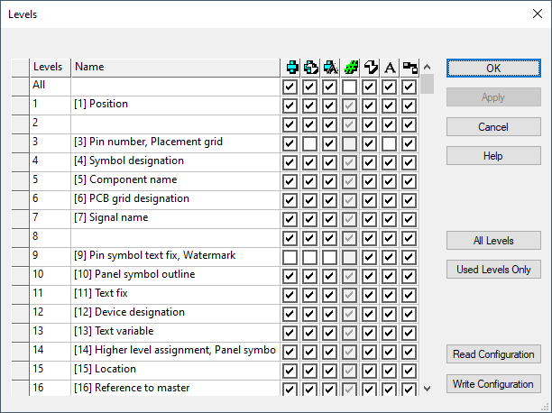
The Levels dialog provides the following functions:
-
Enable, or Disable, the display of individual objects, on each of the 256 levels, by checking (or un-checking) each of the associated boxes.
-
Show or hide a specific type of object (e.g. symbol text), on all levels at once, by checking the appropriate box in the 'ALL' line at the top of the list. If the whole column is un-checked with the 'ALL' option, the column will become inactive and is displayed in gray color.
-
Several columns and/or rows, can be selected at once by left-clicking the mouse on a starting point in the levels column, and dragging it to the final point, to define an area encompassing the desired rows and columns. Right-click anywhere within that area to display the context menu, where you can either Show or Hide the objects on the selected levels.
To display the Levels dialog,
select the View -> Levels... command from the Main Menu bar or use hotkey L.

|
Levels |
|
|---|---|
|
Name |
Defines the plain text name of the level. The name must be unique, may consist of 128 characters and cannot be a purely numeric value. |
|
|
Is the complete circuit diagram symbol, as defined in the database, i.e. with all text. |
|
|
Refers to the graphic of the symbol, without any text. |
|
|
Is the text associated with a symbol. |
|
|
Is the display of empty text locations. |
|
|
Refers to free graphical elements. |
|
|
Are comment texts. |
|
|
Are connection lines. |
|
All Levels |
All levels are displayed. |
|
Used Levels Only |
Unused levels can be hidden by pressing the 'Used Levels Only' button. To display unused levels, right-click on the left (gray) column of the table and select the 'Insert Rows' command from the displayed context menu. |
|
Read Configuration |
A .vis file can be loaded which contains previously saved level settings.
When loading such a visibility settings file using Read Configuration, the Reload level names option is available when switching languages to transfer only the names from the file and not the associated level definitions.
The settings can either be applied by pressing Apply/OK or be ignored by pressing Cancel. |
|
Write Configuration |
The current settings of the dialog can be written to a file with the extension .vis by using the Write Configuration option. |
|
Show/Hide |
By activating Show or Hide from the context menu displayed when right-clicking on the left (gray) column of the table, the different levels can completely be shown or hidden. |
|
Insert Rows/Remove Rows |
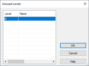
By activating Insert Rows from the context menu displayed when right-clicking on the left (gray) column of the table, unused levels can be displayed. The 'Unused Levels' dialog box appears and the levels can be selected.
By activating Remove Rows from the displayed context menu, the row selected will be removed. |
 Symbol
  Symbol Graphic
  Symbol Text
  Empty Text
  Graphic
  Text
Text  Connections