Defining Components
After having defined the required components, the next step is the preparation of the electrical checks.
Defining Specific Values and Limiting Values on Components
One symbol can be used as the basis for different components. In doing so, only those attributes with specific values or limiting values can be distinguished on the component.
These attribute specific values and limiting values can be defined as follows:
-
right-click on the component and select the command Component Properties... in the context menu,
-
the Component Properties dialog opens,
-
click on the cell Entry of the desired attribute and enter a new value:
Example 1: 'Resistor'

(Component template from database: HSA25100R0J)
Example 2: 'Fuse'
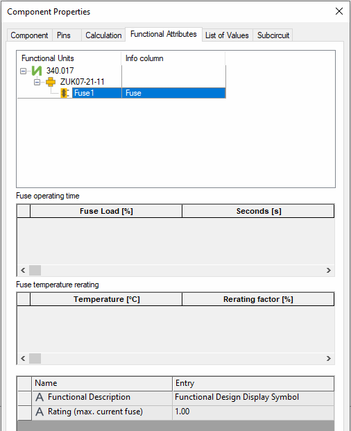
(Component template from database: 340.017)
Note
The number of values for Fuse operating time and Fuse temperature rerating can be supplemented with dummy values. To do so, insert the value 0 in both columns of the attribute to be enhanced.
If you want to exclude an existing value from the check, set the value 0 in both columns for the corresponding values with Fuse operating time or Fuse temperature rerating.
Fuse operating time and Fuse temperature rerating cannot be defined for states of functional units.
Vales can be added or removed when defining functional units.
Example 3: 'Load'
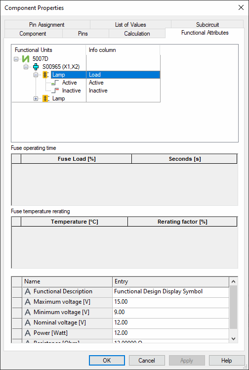
(Component template from database: 5007D)
Example 4: 'Switch'
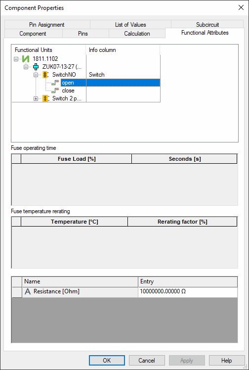
(Component template from database: 1811.1102)
Example 5: 'Coil'
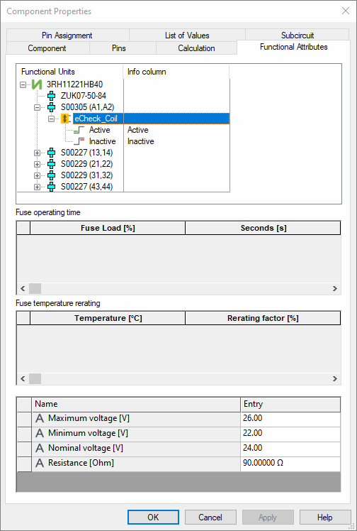
(Component template from database: 3RH11221HB40)
Assigning a 'Symbol State' to the 'Component State'
Note
This step is only required when functional units with states have been added.
Place the required symbols to be assigned to the component on the component sheet.
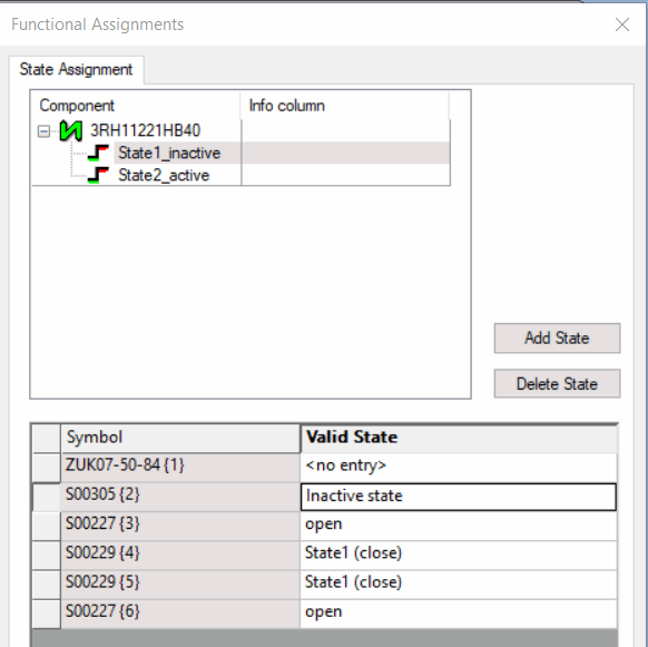
In the following example, the component 3RH11221HB40 is used with the following symbols:
-
ZUK07-50-84
-
S00305
-
S00227
-
S00229
-
S00229
-
S00227

Next assign the individual 'symbol states' to each 'component state':
-
right-click on the component sheet and select the command Functional Assignment... in the context menu,
-
the Functional Assignments dialog opens,
-
click on the button Add State to add one or more 'component states',
-
assign a name to the 'component state' by pressing the F2 key,
-
then select the 'component state',
-
and then, for each 'component state' select for each used symbol the corresponding 'symbol state' from the selection list in the column Valid State.
If no valid state exists, <no entry> must be selected.
The following example shows the valid states for the symbol S00305 {2} on the component:

