Preparing the Electrical Checks
Adjusting Settings for the Electrical Checks
After having added the required functional units to the corresponding symbols and components in the Database Editor, you can switch to the Project mode. Execute the 'Update in Project' command to load all data modified.
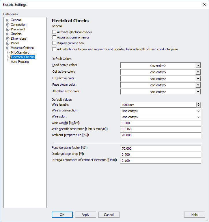
Before starting the simulation, some options and values may need to be adjusted in the Settings.
To open the Settings dialog
-
select the command Tools -> Settings from the Main menu bar or use the hotkey S,
-
and switch to the Electrical Checks page in the dialog box.
Placing and Connecting Symbols
-
Create a new schema sheet,
-
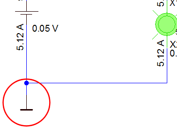
place all required symbols and draw the connect lines,
-
optionally assign various wires, cross-sections, etc.
Note
Add a GND symbol to the circuit to achieve correct results.
Seeing States
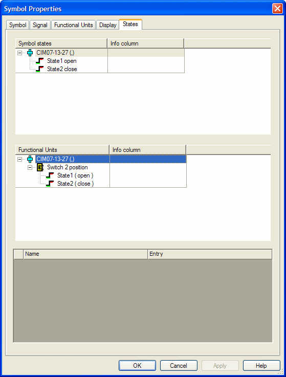
Assigned states can be seen anytime in Project mode.
To see the define states of a symbol:
-
right-click on the desired symbol,
-
select the command Symbol Properties... from the displayed context menu and
-
switch to the States tab of the dialog box Symbol Properties:
To see individual symbol states
-
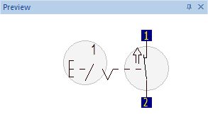
right-click on the desired state and select the command Select State from the displayed context menu:

-
The preview symbol displays the selected state:
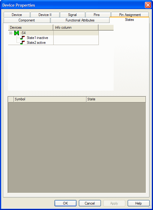
To see the defined state of a device
-
right-click on the desired symbol,
-
select the command Device Properties... from the displayed context menu and
-
switch to the States tab of the dialog box Device Properties:
Seeing Device's Functional Attributes
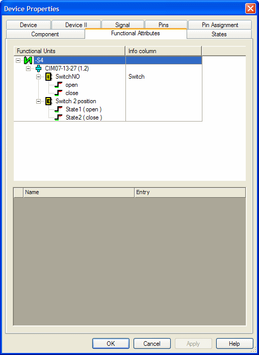
The defined functional attributes of a device can be seen anytime in Project mode.
To see the defined functional attributes of a device
-
right-click on the desired symbol,
-
select the command Device Properties... from the displayed context menu and
-
switch to the Functional Attributes tab of the dialog box Device Properties:
Defining Internal Resistance for Individual Connector Pin Terminals and Pins
In general, a global default value can be defined for the internal resistance of connect elements (e.g. connectors and connections) in the settings (under Settings -> Electrical Checks-> Internal resistance of connect elements [Ohm]:).
From now on it's possible to define different internal resistance values for individual contact elements in the project. These different resistance values are considered later for the calculations.
To define the internal resistance directly on a pin
-
mark the desired device in the workspace and select the command Format -> Device Properties..., or
-
right-click on the symbol, which has been assigned to a component and select the context menu command Device Properties..., or
-
right-click on a single pin or the pin text of a symbol and select the context menu command Pin Properties..., or
-
right-click on the desired device in the project window device tree and select the context menu command Device Properties...,
-
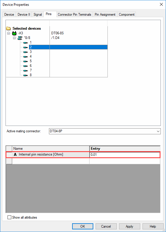
afterward select the Pin tab,
-
right-click on the first available cell in the attribute selection list and select the attribute Internal resistance on pin [Ohm]
-
enter the desired resistance for the internal resistance on the pin in the column Entry:
In doing do, the following rules are valid:
-
If a connector with more than one pin is placed as a complete connector and no wires are connected to the pins, the default value is used for the calculation.
-
If no internal resistance values are defined on both plugged pins, the default value is used for the calculation.
-
The internal resistance can only be defined on pins / connector pin terminals, i.e. the default value is used for the calculation with symbol-oriented work.
-
If wires are connected to a complete connector, a unique current path assignment is ensured. In this case, the resistances on the pins are used for the calculation.
Note: Only the values of the first pin are used for display! If one wants to see the voltages and currents of all pins, this must be done using the Pin Properties.
-
If a connector pin terminal is assigned to the connector pin, then the internal resistance of the connector pin terminal is used.
The internal resistance for the connector pin terminal can be defined on the component pin in the Database Editor.
If no internal resistance is defined on the connector pin terminal, the value from the connector pin is used.
Note: The rules 2-4 are valid here!