
Functionality
Functionality within the Terminal Plan
The arrangement of the terminals can be moved by simply using the Drag&Drop functionality to select one of the lines in the terminal plan and move it to a new position. Please notice that all lines belonging to the terminal are moved, not only the selected line.
Lines can be moved to another sheet by positioning them above or below the rest of the lines. To move a line to the previous sheet, it must be placed in front of the first line of the sheet. It will then re-appear as the last line of the previous sheet and will be replaced by the line that previously was at the bottom of the previous sheet. Conversely, moving it to the bottom will move it to the next sheet.
These modifications are online updated in the Device tree of the schematic diagram.
The Insert Terminal Plan command selected from within the Device tree using the right mouse button can be activated on an individual device. This command creates an own terminal plan sheet for the selected device. This functionality bears two further options: If the terminal plan has already been created for the selected device, this command updates the existing plan. What is more, if the command creates a new terminal plan sheet this sheet will be actively displayed in the Drawing Area.
The pin name (number) of the terminal, the destination device, the destination pin-numbers, the signal name and the item designation of the terminals can all be changed in the Terminal Diagram. Cables, conductors and signals can be modified in the Connection dialog by right-clicking on any of them to display the dialog box. Any changes made are immediately reflected on all other sheets.
Note
Regarding busbars, the Terminal Table shows the pin names of busbars, but not their connection targets.
Sort terminal strips by
Note
If necessary, it must be sorted again after switch of variants / options
None
The terminal strips are not sorted.
Pin name
The terminals are sorted based on pin names. The first variable pin of each terminal is taken as a criterion for the sorting process.
Cable
Cables connected to the terminal strip are sorted by the cable's device designation. The terminals are then sorted based on the order of the conductors in the cable description.
Placement
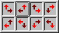
The terminals are sorted based on their location in the schematic diagram. The sheets are sorted in ascending order first and then different sorting options are available for sorting within the sheet, for example [upward, to the right] or [to the left, downwards], etc. The black arrow indicates that every terminal is selected in that direction as you move in the direction of the red arrow.
Jumper
The terminals are sorted to provide the optimal arrangement of jumpers (jumpered terminals are placed next to each other, minimum number of jumpers at the first terminal of a block).
Sort file
Terminals within a terminal strip can be sorted in the tree view by user-defined sorting criteria. The definition of the sorting criteria occurs by using a sorting file.
Every line with content represents an own sorting criteria within the sorting file.
The following (even multiple) placeholders can be used as sorting characters for each sorting criteria:
# - numeric characters (digits 0-9)
& - alpha-characters (all letters)
! - alphanumeric characters (all letters and all digits)
$ - special characters (all characters which are no alphanumeric characters)
? - arbitrary characters
Note
-
The sorting criteria is read line by line from top to bottom and from left to right
-
Space characters at the beginning and/or the end of a sorting criteria are ignored
-
When multiple terminal names apply to a sorting criteria, they will additionally be sorted ascending by their terminal name
-
A combination of placeholders and arbitrary characters is also possible (Example:K?)
-
Lines which start with an apostrophe will be evaluated as comment (Example:' A comment can be found here)
-
The sorting file supports the following file formats:
-
UTF-8
-
UTF-16
-
UTF 16 - Big-Endian
-
ANSI/ASCII
-
Example
Terminal names within the terminal strip before sorting:
-
A5
-
23A
-
A+2
-
10A
-
A2
-
k1
-
z11
-
a11
Definition in the sorting file:
-
A#
-
A$#
-
##A
-
?!
New order after use of sorting file:
-
A2
-
A5
-
A+2
-
10A
-
23A
-
k1
-
a11
-
z11
If a terminal plan is generated of all terminals, the terminal strips are sorted according to the Device tree view and the plan is subsequently generated. If terminal plans already exist, these are updated, i.e. their sheets are not modified.
The Sort command is available in the Sheet tree view. If only terminal plans are selected, the sheets are sorted according to the terminal strips' order in the Device tree.
Compress the Terminal Plan
-
The Autocompress option in the Terminal Plan dialog allows to minimize the number of lines in the Terminal Plan. That means, if the number of internal and external connections is different, connections of the side with the higher number of connections, are moved to the side with the smaller number of connections.
-
The Unique Connections option generates the terminal plan by using unique point-to-point connections.
-
The checked Wires in plan option outputs the wires used in project in the terminal plan. For the attributes 'Device designation of cable (int.)' / 'Device designation of cable (ext.)' and/or 'Item designation of cable (int.)' / 'Item designation of cable (ext.)', the system displays the name of the folder under which the wires in project are stored in the Device tree. Assigning the folder 'Wires' to the internal / external side of the terminal plan is impossible. The user can only assign single wires.
-
Text nodes are used to display signals in the terminal plan. If the user doesn't want to display a signal, the text node can either be removed or switched off using the levels option. User-defined signals have higher priority than system-generated signals. These can be switched off using the Only user-defined signals option. If this option is active, system-generated signals are not displayed in the terminal plan.
Definition of internal and external side
The side is determined by the EXTERNAL or INTERNAL function (database field) at the symbol node or the .EXTERN or .INTERN attributes of conductors or cables.
If it is not defined, the side is defined based on the item designation (same higher level assignment and location as the terminal is interpreted as being internal, otherwise external).
Regarding terminals with assigned Internal/External connection attributes, the wiring direction should always be from the same side.
Note
The Internal and External connection attributes of connected conductors are placed on the conductor ends.
Example
The connection -X1:1 ~ -K1:A1 (conductor-W1:1) shall be displayed on the external side of terminal plan -X1. The conductor end -X1:1 of conductor-W1:1 thus is assigned the External connection attribute.
Priority in the terminal diagram
The following priorities apply for the definition of the side in the terminal diagram:
-
Side definition on the conductor.
-
Side definition on the cable.
-
Definition on the terminal pin.
-
Definition on the basis of the item designations.
Jump command to the terminal
A terminal in the schematic diagram can be quickly accessed from the Terminal Plan by double-clicking the terminal name (number) in the Terminal Plan, or by right-clicking on the terminals location in the Terminal Plan and by then selecting 'Jump' from the displayed context menu.
Jumper functions
The Jumper for terminal attribute on a conductor or cable allows for the placement of a jumper in the Terminal Plan.
-
The Jumpers by Connections option defines the setting of the jumpers being based on the graphical connections.
-
If the in line option is checked, the graphically connected terminal pins will be put together on creation of a terminal plan (also 'crossing' equivalent pin) and jumpered sequentially. This might result in the terminal plan displaying a jumper from pin to pin although exactly this graphical connection does not exist.
-
If the Jumpers by Attributes option is checked, the jumpers are defined by the graphical connections and the attribute 'Jumper for Terminal' on a cable or conductor, i.e. jumpers are output in the terminal plan as wires and/or conductors.
-
The No Jumpers option defines whether jumpers are output.
Terminals within a terminal strip with the same terminal number can now be assigned jumpers automatically.
With the new functionality Generate Jumpers on Terminals the jumper is placed on the terminal without a connection having to be drawn in the schematic.
To generate jumpers on selected terminals with the same terminal number
-
select the desired equivalent names in the device tree, workspace, terminal plan or terminal table using multi-select,
-
then right-click and select the context menu command Generate Jumpers on Terminals.
To generate jumpers on terminals of a terminal strip with the same terminal number
-
select in the device tree or the terminal table
-
the desired terminal strip,
or
-
the desired terminal strips using multi-select,
-
-
then right click and select the context menu command Generate Jumpers on Terminals.
To generate jumpers on terminals with the same terminal number on every terminal strip in the project
-
right-click on the project name in the device tree,
-
then select the context menu command Generate Jumpers on Terminals.
Note
-
If a graphical connection exists, this is given priority.
-
If no graphical connection exists, the jumpers are placed in the sequence of the terminals in the terminal strip.
-
The following is valid in panel:
-
For jumper connections the wire in the Settings (Settings -> Connection -> Conductors/Wires -> Used Jumper Type) is used.
-
If a jumper is already defined for a signal, this is used.
-
For variants/options the command Generate Jumpers on Terminals is only valid for variant/option currently active.
For jumpers automatically generated with the command...
-
Autoconnect in Panel, or
-
Generate Jumpers on Terminals, the pins are renamed afterward.
The following is valid: If the command Generate Jumpers on Terminals is called up (once again), these jumpers are deleted.
-
-
The Terminal strip section
The List all Devices option, which is unchecked by default and controls whether only terminal strips or all normal devices are listed. Connections going through the device are output as jumpers. Using this option, the user can create an own terminal plan sheet for each individual device by selecting the respective device from the drop-down list. Concerning assemblies, all devices are output in the same terminal plan.
The Item Designation options (Device Designation, Higher Level Assignment and Location) select the terminal strip(s) by their Item Designation part. These fields are only active, if the command has been activated on the Insert Main menu.
Core connection in the terminal plan
Conductors can be assigned a terminal plan. To do so, conductors have to be selected in the Device Tree and by Drag&Drop or by using the command 'Connect Conductors' or 'Connect one-by-one' from the displayed context menu these conductors can be placed on the terminal plan. It is necessary that clear targets exist in the terminal plan.
Possible terminal plan texts which can be assigned the conductors:
-
Item designation (ext.)
-
Pin name (ext.)
-
Conductor name (ext.)
-
Item designation (int.)
-
Pin name (int.)
-
Conductor name (int.)
-
Conductor color (int.)
-
Conductor cross-section (int.)
-
Conductor length (int.)
-
Conductor type (int.)
-
Conductor color (ext.)
-
Conductor cross-section (ext.)
-
Conductor length (ext.)
-
Conductor type (ext.)
-
Device designation (ext.)
-
Higher level assignment (ext.)
-
Location (ext.)
-
Device designation (int.)
-
Higher level assignment (int.)
-
Location (int.)
For displaying shield names of shields being connected to terminals by wires/cables etc. and entered as conductors in the cable column of the terminal plan the following text types are available:
-
Shield name (ext.)
-
Shield name (int.)
Display of cable texts in the terminal plan
Possible terminal plan texts which can be assigned a cable:
-
Item designation of cable (ext.)
-
Device designation of cable (ext.)
-
Higher level assignment of cable (ext.)
-
Location of cable (ext.)
-
Cable type (ext.)
-
Item designation of cable (int.)
-
Device designation of cable (int.)
-
Higher level assignment of cable (int.)
-
Location of cable (int.)
-
Cable type (int.)
Display Individual Terminals in Options
It is possible to individually display terminals in options. The handling is the same as with cables. The individual wires can also be assigned options, or switched on or off.
Note for the terminal plan
In the normal multi-user mode the terminal plan is always calculated as if all options were activated, i.e. blank lines can be generated. In single-user or multi-user exclusive mode the terminal plans are calculated in connection with the options.