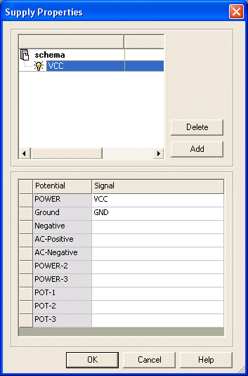
Supply Properties
Using the dialog Format -> Supply Properties in DBE as well as in Project mode it is possible to
-
add an additional supply so that individual components can be assigned to it later on,
-
modify signal assignment (e.g. change and delete default signal assignments for potentials),
-
rename the supply name and/or
-
delete a not referenced (used) supply.
Supplies are graphically displayed by an electrical bulb.
To display/modify the properties of the selected supply:
-
Select Format->Supply Properties from the Main Menu bar.
The following dialog will be displayed:

|
Supply Properties |
||||||||||||||||||||||||||||||||||
|---|---|---|---|---|---|---|---|---|---|---|---|---|---|---|---|---|---|---|---|---|---|---|---|---|---|---|---|---|---|---|---|---|---|---|
|
Delete |
A supply remains existing in the database or the project even if it is no longer required by any component. However, it can be deleted explicitly in DBE or the project.
Deletion of the signal definition of a potential and the complete supply description is only possible, if it is referenced by any pin or component in the database or the project.
The objects that prevent the deletion are reported in the component list displayed in the output window. |
|||||||||||||||||||||||||||||||||
|
Rename |
The name of an existing supply can be modified.
All components and component types assigned to this supply will then indicate the supply with the new name. The signals are not affected by definition of a new name.
An already existing name can also be renamed. The user is informed that the default signals of the potentials in the existing description remain valid.
In the case where the renamed description potentials with signal, the existing supply is extended. |
|||||||||||||||||||||||||||||||||
|
Add |
Select Add to define the name of the new supply in the top left of the dialog.
The name of the supply must not yet exist in the database or in the project. At least one potential must be defined for each supply. |
|||||||||||||||||||||||||||||||||
|
Potential/Signal |
Signals of the new or an existing supply can be added or changed in the bottom section of the table.
The required signal name is assigned to the individual potentials (POWER, Ground, etc.). If necessary, the entered signals are automatically added.
The potential designations are predefined in E3.series, but do not represent a functional relationship.
If the power supply pins are defined in the database, the signals must be defined in accordance with the supply types used in the database field LPINEQV.
When modifying a signal of a power supply, the modification applies to all corresponding supply pins of all components that are assigned to this supply.
NoteDouble-click on the desired signal to display the |
|||||||||||||||||||||||||||||||||
 button. Clicking on this button opens the