
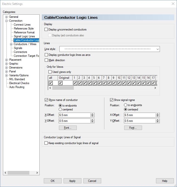
Connection - Cable/Conductor Logic Lines
Changes made to Connection properties, as shown in the following dialogs, only apply to objects that are drawn after changes have been made to the settings, not to existing objects.
|
Cable/Conductor Logic Lines |
|
|---|---|
Display |
|
|
Display unconnected conductors |
Conductors are laid between two pins or component pins in the form of point-to-point connections.
A graphical connection between the pins need not necessarily exist. If it is missing, logic lines can be displayed between the pins by checking this option.
The drop down list allows you to select the line style to be used for logic lines. The default type is dotted.
NoteThe check box Display |
|
Display laid conductors also |
When conductors are laid in connections, it is possible to display the conductor logic lines by using this option.
The logical connect lines are drawn not directly from pin to pin, but represented with the set options in an arch from the start pin to the end pin, so that they are well visible beside the usually orthogonal connection lines.
When additionally activating the Mark direction option, then the direction of the laying path is displayed as an arrow.
Example
|
|
Mark direction |
For many applications, the direction that the conductors were laid between pins is important.
When checking this option, an arrow is displayed at the end point of the logic line to indicate the end point of the conductor.
The distinction between start and end point (end-1/end-2) is also of importance for the assignment of attributes for the processing of conductor ends. |
Lines |
|
|
Line Style |
Defines the line style which shall be used for the |
|
Display |
When this option is active, the logic lines of unconnected
When this option is inactive, the logic lines of unconnected
|
Only for Views |
|
|
Used views only |
In conjunction with the display of multiple connector views, it is often undesirable to display conductor logic lines, for open and placed conductors.
Display of the logic lines can individually be defined for the original and the views 1-99.
Check the desired view in the Only for Views section and activate the Used views only checkbox to have only those view(s) used in the project displayed in the dialog.
The original and the views 1-99 each have a separate column with a checkbox. The first column all activates or deactivates all checkboxes, i.e. views in all columns. By default, the original and all views are activated. |
|
Show name of conductor/how signal name |
If desired, signal names can be displayed in addition to the displayed logic lines.
When these options are checked, further options become active that allow you to define the position and representation of the text. |
|
Position |
The following options are available for the positioning of text:
Text is displayed according to the defined offset and either relative to the end points of the logic line or centered along the line (in this case, X-offset has no impact on the position). |
|
X-Offset |
Offset of the text starting from the point where the graphical pin and the logic line meet.
Alignment of the text depends on the direction of the symbol or the connection direction defined in the database. |
|
Y-Offset |
Defines the distance between the text and the logic line. |
|
Font |
This option opens another dialog for the definition of:
The following text parameters can be set in the Font dialog:
Changes made to the settings only apply when confirmed by pressing either the OK or Apply button in the Logic Lines dialog. |
|
|
|
|
Keep existing |
When this option is active, all displayed logic lines of signals are kept.
See also under: Display |
 s
s