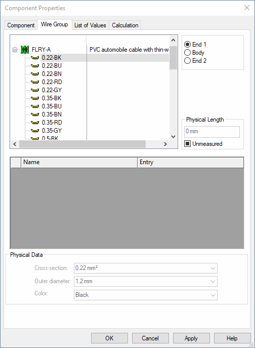
Component Properties - Wire Group
With DBE mode disabled, no modification can be made. The dialog only serves for information on the different database entries.
With DBE mode enabled, the database fields can be modified (see also: Component Properties - Wire Group (DBE mode)).
To display the wire properties of a component,
-
right-click on the component in the Component Tree of the Database Window and select Component Properties... from the displayed context menu.
The following dialog box will be displayed:

The top part of the dialog box displays a Tree View for selection of the wire group and/or individual wires and three radio buttons for the selection of the end or the body of the wire group / wire (End 1 / Body / End 2).
The middle part of the dialog box contains the table for the specification of attributes.
The bottom part of the dialog box contains physical data for the selected conductors.
|
Wires |
|
|---|---|
|
End 1/Body/End 2 |
Defines which attributes (the end or the body of the wire group) will be shown in the section below (Name). |
Physical Length |
|
|
Unmeasured |
Defines the physical length of the routed length with wires in the panel or formboard.
The field for the physical length is active only if the Unmeasured option is checked.
When the 'Unmeasured' option is activated, the wire length is not determined by the system but the wire length defined in this field is used.
Rules
|
|
Name |
The Name fields display additional information that can be associated with a wire group / wire, e.g. Description, Material, etc. |
|
Entry |
The Entry fields display corresponding information defined for that property within the project. |
Physical Data |
|
|
Cross-section |
Defines the wire's cross-section. |
|
Outer diameter |
It's possible to also define the wire's outer diameter which enables a more precise calculation of the cable duct's filling degree.
The outer diameter is calculated as follows:
When no outer diameter is defined in the database, the cross-section (with wire insulation factor) is used.
The outer diameter is also used when calculating the filling degree of cable ducts, when displaying connections in 3D panel, when exporting in STEP format and with the COM methods netseg.GetOuterDiameter and job.GetOuterDiameter. |
|
Color |
Defines the wire color. |