Definition in Database - MIL Connector Symbol
General Information
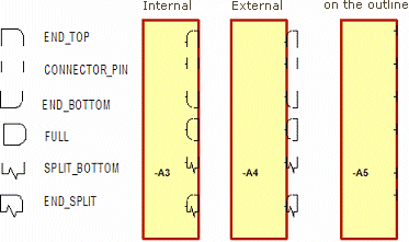
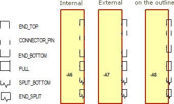
For the different representations of the connectors, special symbols are required:
-
symbols for PLUGs and RECEPTACLEs
-
symbols for block PLUGs and block RECEPTACLEs
-
for placement outside the block
-
for placement inside the block
-
for placement directly on the block's outline
-
PLUG

RECEPTACLE

Symbol Definition
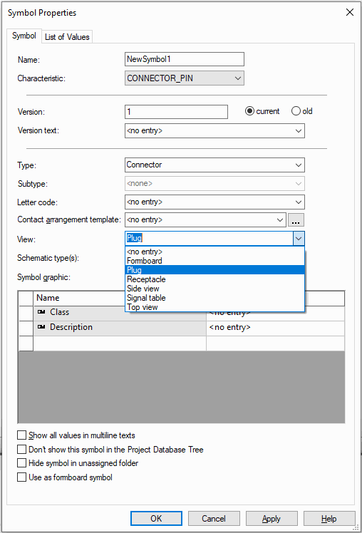
Connector pin symbols are defined in the Database Editor by the entry in the "type" field of the Symbol Properties through its type, e.g. a connector symbol has the "connector" or "block connector" type assigned. Using View and Characteristic entries additional properties can be specified.
The following views can be assigned to "connector" symbols:
-
Plug
-
Receptacle

The following views can be assigned to block connector symbols:
-
Plug
-
Plug external
-
Plug internal
-
Receptacle
-
Receptacle external
-
Receptacle internal
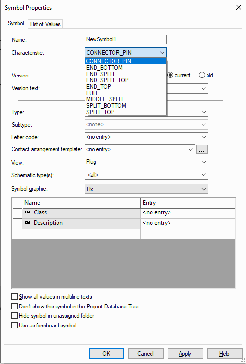
As soon as one of these views is selected, it is possible to choose on of the following characteristics from a drop-down selection list:
|
Characteristic |
Description |
|---|---|
|
CONNECTOR_PIN |
normal pin (open on top/on bottom) |
|
END_BOTTOM |
lower end (open towards top) |
|
END_SPLIT |
upper end ("broken" towards bottom) |
|
END_SPLIT_TOP |
lower end of connector with break-up edge above |
|
END_TOP |
upper end (open towards bottom) |
|
FULL |
complete connector view |
|
MIDDLE_SPLIT |
connector with break-up edges above and below |
|
SPLIT_BOTTOM |
lower end ("broken" towards top, open towards top) |
|
SPLIT_TOP |
connector without defined end with break-up edge above |

Additional graphics can then also be defined. For example, it is possible to add/edit the female and male connector pin graphics that can be associated with the view.
See also: MIL-Standard Toolbars
Two points can be defined for the symbols, that represent the start and end point of the graphic connect lines between the symbols. The origin and the node position are used as default (similar to the original symbol).
The connector symbol definition is finished and the MIL Standard symbol can be saved to the database.
Note
To be able to use the MIL symbols on a connector, a complete 'symbol set' must always be generated. This 'set' must contain 6 symbols with the same base name but different characteristics, e.g. MilBlockPlug with characteristics CONNECTOR_PIN, END_BOTTOM, END_SPLIT, END_SPLIT_TOP, END_TOP, FULL, MIDDLE_SPLIT, SPLIT_BOTTOM and SPLIT_TOP.
Summary
-
Connectors can be created with both normal and MIL symbols so that they can be displayed both ways.
-
Connectors can be created to display only normal pin symbols by only defining normal pin symbols.
-
In order to have the ability to display block connectors on the inside, outside and edge of the block, three connector pin symbols must be defined for the block, i.e. one for internal display, one for external and one for display on the block outline.
-
If only one type of block display is required, then only one type of MIL block symbol is required, e.g. inside.
-
Only the base free and block MIL symbols are required for the connector definition, i.e. CONNECTOR_PIN. The remaining symbols, END_BOTTOM, END_SPLIT, END_SPLIT_TOP, END_TOP, FULL, MIDDLE_SPLIT, SPLIT_BOTTOM and SPLIT_TOP are selected automatically, by the MIL functionality, when a connector is placed in a project.
-
If male and female graphic displays are not required, there is no need to create them as part of the connector pin symbols.