gets better fit and impedance control for complex flexible PCBs in metrology instruments using CR-8000
Flexible and flexi-rigid PCBs are integral components within many of Renishaw’s products, and detailed signal integrity analysis is needed to ensure high speed digital signals can be transmitted with minimal distortion. Renishaw migrated to Design Gateway and Design Force, part of Zuken’s CR-8000 PCB design suite, primarily to help with the design and analysis of next-generation flexible PCBs.
Working in 3D for the first time, Renishaw’s PCB designers noticed a host of benefits, including fixing housing fit issues upfront and easier component placement. They also boosted their controlled impedance routing for high frequency signals using electromagnetic field solvers in Design Force. Working in 3D has enhanced collaborative engineering within Renishaw.
Results
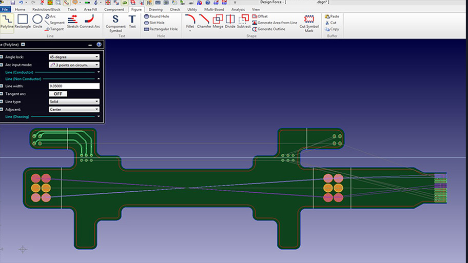
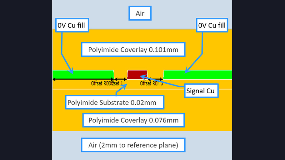
Design Force offers easier controlled impedance routing for high frequency signals using electromagnetic field solvers.
Controlled impedance routing is a prerequisite for good digital circuit signal integrity, and signals – particularly high frequency ones – require constant characteristic impedance from driver to receiver. Renishaw uses Zuken’s CR-8000 suite for controlling impedance. Constraint Manager is used to specify the limits of characteristic impedance and Lightning is used to create impedance templates. This allows them to select a group of nets, using a net class, and then use the field solver to automatically calculate the impedance specified – adjusting the track widths to match.
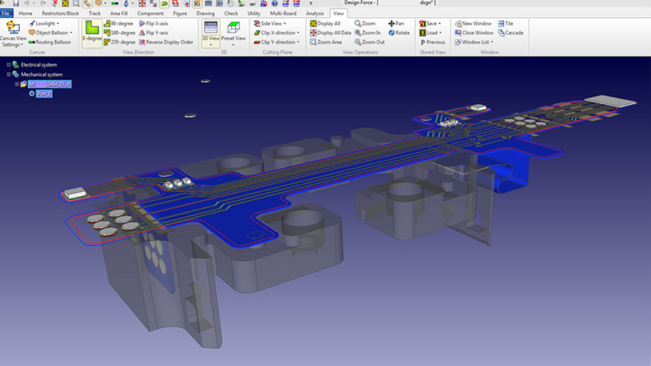
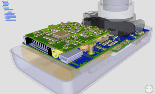
A major benefit of the migration to CR-8000 is that Renishaw’s PCB designers have the ability to visualize and manipulate board designs in 3D.
Pete Leonard, Electronic Design Manager for Group Engineering, Renishaw, comments: “We can place components in a 3D environment, taking into account any constraints that may have come over from our mechanical engineers and then switch back to 2D for routing.
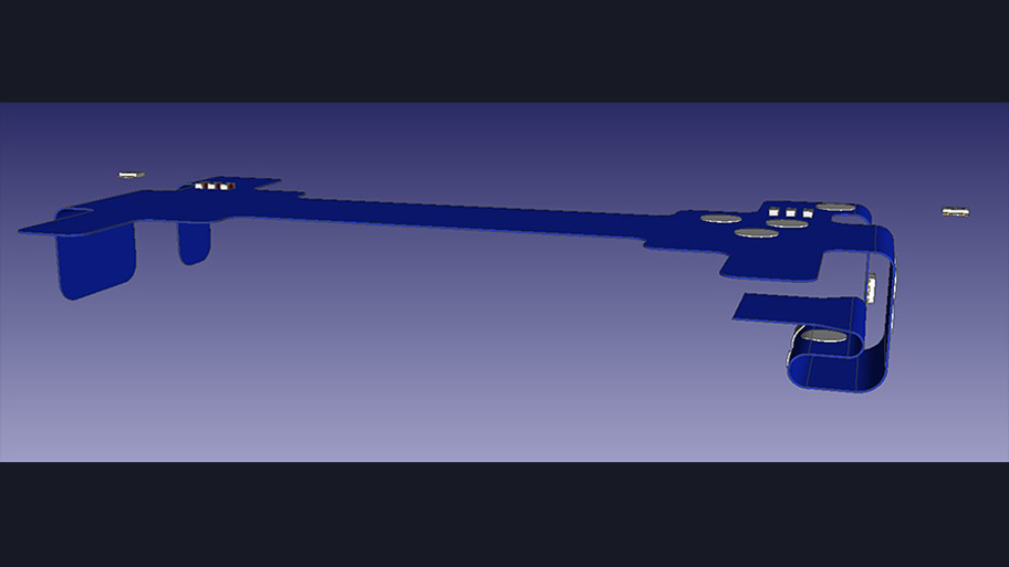
What if’ scenarios can be viewed by bending the flexible PCB.
During the design of the flexible PCB, Renishaw’s PCB designers created a user-defined layer called ‘BendLine’ (a case- sensitive reserved name). On this BendLine layer, polylines were drawn to represent the axes around which the flexible PCB needs to bend. Properties such as bend direction, angle and radius were then applied to each of the polylines. Renishaw’s PCB designers were then able to move components around in this 3D environment. They were also able to import (via .stp file) the housing around which the flexible PCB must bend.
Renishaw discuss their relationship with Zuken
Play
2:59
Play
3:31
Play
3:19
Our use of Design Gateway and Design Force within Zuken’s CR-8000 platform has enhanced the way our PCB designers and mechanical design engineers work together when developing complex flexible and flexi-rigid PCBs.
Pete Leonard, Electronic Design Manager for Group Engineering at Renishaw
How Zuken have helped Renishaw
Products used
CR-8000, Design Gateway, Design Force
Industry
Medical, Machinery, Instrumentation
Company profile
Renishaw is a global company with core skills in measurement, motion control, spectroscopy and precision machining. Their products are used for applications as diverse as machine tool automation, co-ordinate measurement, additive manufacturing, gauging, Raman spectroscopy, machine calibration, position feedback, CAD/CAM dentistry, large scale surveying and stereotactic neurosurgery.