'Net Number' Attribute
The attribute Net Number is an information carrier within a net, similar to a signal. In contrast to a signal, the net number is less important and only under certain conditions inherited.
The attribute Net Number is ideally suited for working with different types of schematics (in the example used, these are the functional schematic and the integrated schematic).
Note
Owners of the attribute Net number:
-
Cable conductor
-
Connector pin
-
Block pin
-
Device pin
-
Net
Adding the Attribute 'Net Number'
For editing the attribute Net Number there are several possibilities:
Over the net:
-
right-click on the desired connection,
-
select the command Connection Properties… from the displayed context menu,
-
select the tab Net,
-
then select the attribute Net Number in the table under Net Properties and activate the check box,
-
define a designation for the net number under Entry.
Over the wire (cable conductor):
-
right-click on the desired wire in the Device Tree,
-
select the command Wire Properties… from the displayed context menu,
-
select the tab Wires,
-
then select the attribute Net Number in the table under Name and activate the check box,
-
define a designation for the net number under Entry.
Note
The net number cannot be edited on a pin.
Inheritance Rules
-
From net to "pin" (always if the attribute is changed in the net segment)
-
From net to physical connector (physical connector = conductor, hose, tube)
-
Over signal cross-references between two nets
-
Over signal-equivalent pins to other equivalent pins
-
If net segments with different net numbers are connected with one another, a query follows asking which net segment shall be valid for the new net segment.
-
Over plugged connectors (for single pins)
Note
There is no inheritance from pin to net (segment) if the net (segment) already has a different value for the attribute Net Number. This is because the pins have different values for the attribute Net Number within the net.
If all connected pins in a net have the same value for the attribute Net Number, the attribute is inherited by the net.
Example of Usage
|
Functional Schematic |
Integrated Schematic |
|---|---|
|
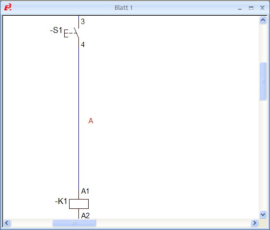
The functional schematic is the graphical display of an electrical circuit, on which the devices used are incorporated. |
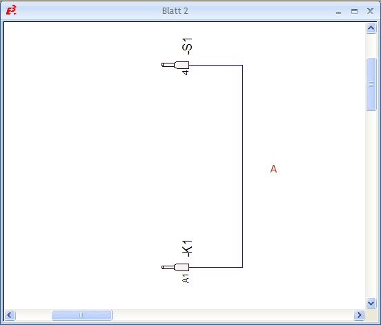
A second graphical display can be used as a wiring diagram. In the integrated schematic the pins of the functional schematic are placed on separate sheets as pin views. For example, a wire end ferrule can be used as a symbol for the pin view. |
Preparation |
|
|
|
For the pin view in the integrated schematic a predefined symbol can be selected from a drop-down list in the Settings under Placement -> Symbols -> Symbol Views in the section Pin View Symbols under For device pins. |
Step 1 |
|
|
|
|
|
In the functional schematic (Sheet 1) the attribute Net Number with the entry A is added to the net segment between the devices -S1 and -K1 |
New pin views are placed on the integrated schematic (Sheet 2) for pins 4 (device -S1) and A1 (device -K1).
Likewise, the connection between both pins as well as the attribute Net Number with the entry A must be manually added to the connection. |
NoteWhen working with several schematic views, uniformity between the different schematics must always be ensured. This means modifications to one schematic must be adapted for all other schematic views. |
|
Step 2 |
|
|
|
|
|
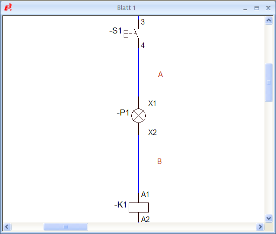
An additional device -P1 is placed on the connection between devices -S1 and -K1.
The upper net segment retains the net number A, while the lower net segment is assigned the net number B. |
The attribute Net Number is not inherited from the net in the integrated schematic because the pins have different values within the net.
|
NoteDifferent values for the attribute Net Number can now be assigned to both net segments in the functional schematic. |
|
Step 3 |
|
|
|
New pin views must be placed on the integrated schematic (Sheet 2) for pins X1 and X2 of device -P1. Likewise, the net segments together with the net numbers corresponding with the functional schematic template must be manually adapted. |
Net Number Conflict
When connecting two individual connect lines that both have a different 'Net number' attribute assigned, a conflict is reported.
The system displays a corresponding message asking the user to select the 'Net number' attribute to be used for the complete connection element.


