Multiple Wire Crimps
For assignment of connector pin terminals on pins, E3.series now offers the possibility to control whether
-
a connector pin terminal per
-
multiple wire crimps are allowed
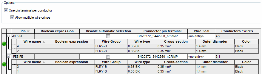
Multiple wire crimps are defined as several wires connected to a connector pin terminal (according to the definition of the connector pin terminal)
Requirements
The following check boxes must be active in the settings under Settings -> Connection ->
þ Use physical data of cavity part models instead of device model
þ Use physical data of
Examples
The following examples have the same initial situation.
On a connection between two devices, the conductors shall, depending on the state of the check boxes
-
One pin terminal perconductor
-
Allow multiple wire crimps
be connected on one or appropriately several connector pin terminals. The state of the check boxes is changed in the Device Properties - Connector Pin Terminals.
Note
The inclusion of conductors on the connector pin terminal is affected by following criteria:
-
Cross-section definitions (min/max/total cross-section and number of wires)
-
Filter attribute (if defined)
-
Lowest appropriate minimum cross-section
-
Appropriate value of numbers of wires
Example 1
In this application example,
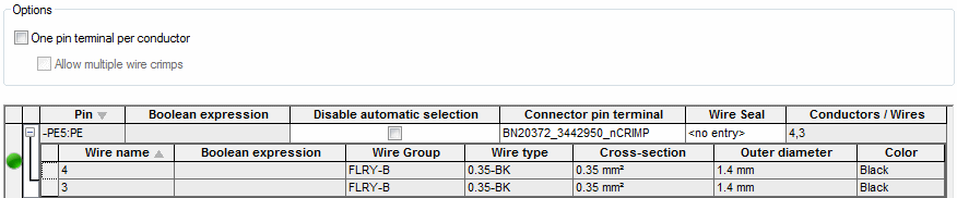
Example 2
In this application example, exactly one
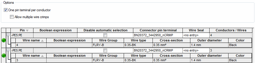
Example 3
In this application example, the