Opening, Editing and Navigating 3D Sheets
Opening Panel Sheet in 3D
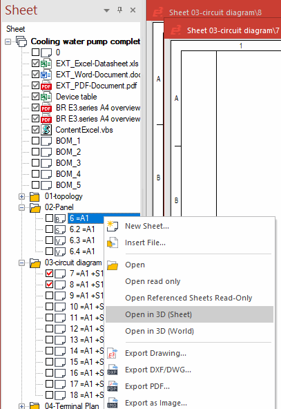
To open a panel sheet in 3D,
-
select the Open in 3D (Sheet) or Open in 3D (World) command from the context menu of a panel sheet in the Project Window's Sheet tree view, or
-
activate the 3D Sheet
 or 3D Panel World
  button in the Panel Toolbar.
Note
Shared sheets cannot be displayed three-dimensionally.
Navigating within 3D View Using Mouse
For navigating within the 3D view, the mouse keys are used as follows:
|
Mouse Assignments |
Function |
|---|---|
|
Click left mouse button |
Selects object. |
|
Click and hold left mouse button |
Move mouse horizontally to rotate 3D world on Z axis. Move mouse vertically to rotate 3D world on X and Y axes. |
|
Shift + click left mouse button |
Add object to current selection or remove it from the selection. |
|
Ctrl + click left mouse button |
Jumps to the tree view. |
|
Click right mouse button |
Calls up object menu. |
|
Click and hold right mouse button |
Moves the 3D world on the X and Y axes. |
|
Mouse wheel |
Zooms in/out Click and hold mouse wheel to define a zoom rectangle (like in 2D). |
|
Click and hold right and left mouse buttons simultaneously |
Rotates complete 3D world. |
Navigating within 3D View using Toolbar
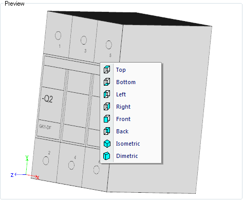
With active 3D display mode a rotation of an object to the appropriate view (top, bottom, left, right, front, back, isometric, dimetric) is possible via symbols. For this, there is the toolbar 3D-View.
This function is additionally available within the preview window of following dialogs:
-
Devices - Shape
-
Devices - Slots/Pins
-
Devices - Contour
-
Model Properties - Shape
-
Model Properties - Slots/Pins
-
Component List
For using it, right-click any area within the preview window:
Editing Objects in 3D View
All commands (like Place, Move, Rotate and so on) are possible in both 2D as well as 3D view.
Tips for placing model origins on slots:
-
On point slots, models can be placed (rotated/tilted) in any view.
-
On line slots, models can only be placed in the top view as long as the justification is the same for both models.
-
On area slots, models can be placed (rotated/tilted) in the top and rear views.
Models Can Be Set as Transparent or Invisible in the 3D View
Note
It is not possible to place, move or rotate objects with the modules E3.redliner, E3.view and E3.viewPlus.
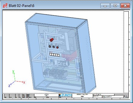
In the 3D view models and their mounted devices can be set as 'Transparent' or 'Invisible'. In doing so, panel doors or miscellaneously placed elements can be made invisible in a closed panel so that one has a better view of the desired area.
Note
-
Connections on panel sheets cannot be set as 'Transparent' or 'Invisible'
-
When importing sub-circuits or using Cut&Paste/Copy&Paste, the state is set to visible once again.

To realize this functionality, there is the context menu command Transparency in 3D.
Prerequisite: This is valid for the following models
-
For all models in the tree structure Panel - Placed
-
For all models placed on the panel sheet in the 2D view
-
For all models placed and visible on the panel sheet in the 3D view
Note:
If the model placed on the panel sheet has already been set/defined as transparent or invisible, the context menu command can only be called up in the 2D view or in the tree structure Panel - Placed.
To set the visibility of a model
-
right-click on the desired model(s) and move the mouse cursor over the context menu command Transparency in 3D
-
the following modes are available for selection under Transparency in 3D:
-
Visible/ Transparent / Invisible
Example "Invisible"
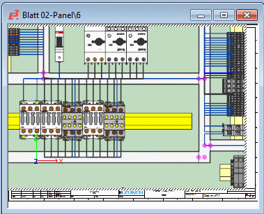


-
... with Mounted Devices Only the selected model(s) with mounted devices are invisible in the corresponding mode.
Example "Invisible with Mounted Devices"


-
... except Selected Devices All models, except the selected model(s) are invisible in the corresponding mode.
Example "Invisible except Selected Devices"


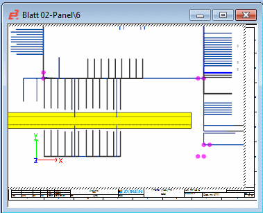
-
-
... except Selected and Mounted Devices All models, except the selected model with mounted devices are invisible in the corresponding mode.
Example "Invisible except Selected and Mounted Devices"


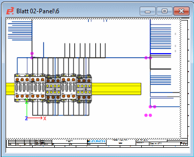
-
To select all models and mounted devices in the entire project, proceed as follows:
- right-click on the project name in the Panel - Placed tree,
- select the command Visible / Transparent / Invisible from the displayed context menu.
Routing in 3D View
By defining the routing pathways (placing cable ducts), wires can also be routed in 3D as in 2D.
Tips for autoconnecting
-
Autoconnect in the panel can likewise be routed through pivoted (tilted) cable ducts. In this respect a cable duct is considered a wiring pathway. This means a wire can arbitrarily enter and exit a cable duct, i.e. entrance through the floor is also possible.
-
The wiring pathway runs along the connection direction up to the point where it drops perpendicular to the middle of the cable duct. This means it always forms a corner perpendicular to the cable duct.
-
The wire is always routed to half the height of the cable duct.
Tips for backplane wiring
-
In 2D view, the wire is routed based on two cable duct combs on the Z axis in the distance defined under Settings -> Panel -> Connection ->Backplane connection distance. In 3D view, the wires are always routed through the backplane in the defined Backplane connection distance based on the orientation of every single wiring comb, i.e. along the negative normal vector of the comb. For wiring combs in the right side wall, the wires lead to the right of the comb.