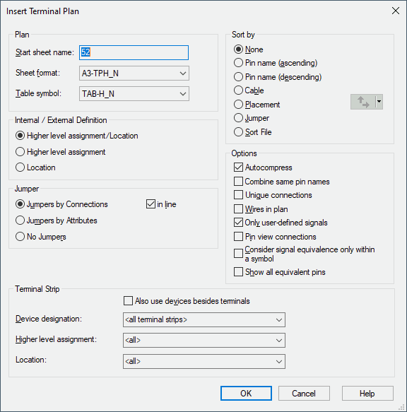
Insert Terminal Plan
To add a terminal plan to the drawing,
-
either select Insert -> Terminal Plan on the Main Menu bar, or
-
select one or several devices and/or terminals in the Project Window's Tree View and select Insert Terminal Plan from the displayed context menu. The entry fields for device designation, higher level assignment and location will then be inactive.
The following dialog will be displayed:
Jumpers in the Terminal Plan
Default jumpers are displayed as follows:
-
in the default symbol color defined in the configuration database;
-
with a line width of 0.1 mm;
-
with a solid line.
The new values become active after first updating the terminal plan. Furthermore, terminal plans with jumpers must be recalculated after changing the default symbol color so that the jumpers are displayed in the desired color.
These values can be defined for user-defined jumper symbols.
Terminal Plan for Connectors
The terminal plan for connectors bears several special characteristics compared to normal components or terminal strips:
-
The internal side always displays the plugged pin.
-
The external side always displays the connected end.
-
Internal/external definition on terminal plan texts is not active.
-
Connectors can be selected in the terminal plan dialog, when List all devices is checked.
Busbars in the Terminal Plan
Regarding busbars, the Terminal Table shows the pin names of busbars, but not their connection targets.
|
Insert Terminal Plan |
|
|---|---|
Plan |
|
|
Start sheet name |
Defines the new sheet name.> The created terminal sheets are not sorted automatically, but using the Sort command in the Sheet tree view. |
|
Sheet format |
Defines the sheet format to be used, selectable from a drop-down list. All available sheets formats, in the active symbol database will be listed. |
|
Table symbol |
Symbol used for the line representation in the terminal plan. All available line representations, in the active symbol database, will be listed. |
Internal/External Definition |
|
|
Higher level assignment/Location
Higher level assignment
Location |
Depending on the state of the selection box, external / internal pin terminals are determined. Following display options are available:
In the Settings - Terminal Table a presetting for the selection box can be defined.
Examples for single display options can also be found here. |
JumperThe Jumper for terminal attribute on a conductor or cable allows for the placement of jumpers in the Terminal Plan. |
|
|
Jumpers by Connections |
When this option is checked, setting of the jumper connections is based on the graphical connections. |
|
in line |
If this option is activated, the graphically connected terminal pins will be put together on creation of a terminal plan (also 'crossing' equivalent pin) and jumpered sequentially.
This might result in the terminal plan displaying a jumper from pin to pin although exactly this graphical connection does not exist. |
|
Jumpers by Attributes |
When this option is checked, the jumpers are defined by the Jumper for terminal attribute on a cable or conductor.
With this option checked, only connections that have this attribute assigned are listed in the terminal plan. Fix connections without this attribute assigned are not output as connections in the terminal plan. |
|
No Jumpers |
No jumper is set. |
Sort by |
|
|
None |
The terminal strips are sorted by their order in the Device tree. |
|
Pin name (ascending) |
Terminal plan rows are sorted ascendingly by pin names. The first variable pin of each terminal is taken as a criterion for the sorting process. |
|
Pin name (descending) |
Terminal plan rows are sorted descendingly by pin names. The first variable pin of each terminal is taken as a criterion for the sorting process. |
|
Cable |
Cables connected to the terminal strip are sorted by the cable Item Designation. The terminals are then sorted based on the order of the conductors in the cable description. |
|
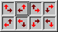
Placement |
The terminals are sorted based on their location in the schematic diagram. The sheets are sorted in ascending order first and then different sorting options are available for sorting within the sheet, for example [upward, to the right] or [to the left, downwards], etc. The black arrow indicates that every terminal is selected in that direction as you move in the direction of the red arrow.
|
|
Jumper |
The terminals are sorted to provide the optimal arrangement of jumpers (jumpered terminals are placed next to each other, minimum number of jumpers at the first terminal of a block). |
|
The terminal strips are sorted by the Sort file.
The sort file can be defined in the settings (under Placement -> Terminal within the area Sorting of terminal strip) under Sort file name:. |
|
|
Autocompress |
Optimizes the rows in the terminal plan to one row per connection. This is especially useful in case no external destination is available. |
|
Combine same pin names |
This option causes that all connections to terminal pins are handled collectively with the same name and, according to other settings (e.g. Autocompress, etc.), that they are arranged to the terminal plan rows. That is why the display of disconnect terminals and multiply displayed terminal symbols of the same terminal pin is optimized in the terminal plan.
In such cases the signal is only displayed, if it is unique (external signal = internal signal).
NoteWith the Combine same pin names option checked, it is, for example, impossible to handle both terminal levels with the same terminal name regarding double-deck terminals. Else, they would be merged in the terminal plan. When, however, different terminal names are used for the levels (e.g. 1a, 1b), this operation works correctly. |
|
Unique Connections |
Generates the terminal plan by using unique point-to-point connections. |
|
Wires in plan |
If this option is activated, the wires used in project will be output in the terminal plan.
For the attributes 'Device designation of cable (int.)' / 'Device designation of cable (ext.)' and/or 'Item designation of cable (int.)' / 'Item designation of cable (ext.)' the system displays the name of the folder under which the wires in project are stored in the device tree. |
|
Only user-defined signals |
A text node is used to display the system-generated signal (#) in the terminal plan. If the user does not want to display the signal, the text node can either be removed or switched off using the levels option. User-defined signals have higher priority than system-generated signals.
These can be switched off using this option.
If this option is active, system-generated signals are not displayed in the terminal plan. |
|
Pin view connections |
Pin views can be used to graphically display duplicate connections between the same pins. They can also be used to multiply display a single graphic connection as view, for a clearer overview.
NoteIf 2 connections, that are both connected to a pin view symbol, start from a terminal symbol, these connections are also output with the option switched off. |
|
Consider signal equivalence only within a symbol |
When this option is checked, signal-equivalent double-deck terminals are displayed in the terminal plan on the level on which they are actually plugged.
When this option is unchecked, name-equivalent and equipotential pins are displayed in the terminal plan as if they were plugged on the same level.
NoteThis option only has an effect if Jumpers by Connections is activated as well. |
|
Show all equivalent pins |
When this option is activated, all pins are shown in the terminal plan, even if the pins are equivalent. |
Terminal Strip |
|
|
Also use devices besides terminals |
If this option is inactive (by default), terminal plans are generated only for terminal strips of the corresponding selection.
If this option is active, terminal plans are generated for all devices that are listed in the drop-down list.
It is thus possible to create terminal plans of normal devices:
NoteConnections going through the device are output as 'jumpers'. |
|
Device Designation |
Selects the terminal strip(s) by their Device Designation. This field is only active, if the command has been activated on the Insert Main menu. |
|
Higher Level Assignment |
Selects the terminal strip(s) by their Higher Level Assignment. This field is only active, if the command has been activated on the Insert Main menu. |
|
Location |
Selects the terminal strip(s) by their Location. This field is only active, if the command has been activated on the Insert Main menu. |