Export VRML Files
Exporting Virtual Reality Modelling Language Files is only possible on active panel sheets!
3D data can be exported in VRML format (Virtual Reality Modelling Language) in E3.panel. This 3D panel information can then be displayed in programs supporting this format.
To export a panel sheet or a part of a panel sheet as VRML file,
-
select File -> Export -> VRML... from the Main Menu bar and
-
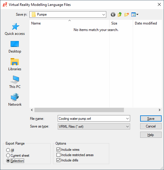
complete the following dialog box:

The system always starts the dialog in the directory defined in the Settings' Default Directory page.
|
Virtual Reality Modelling Language Files |
|
|---|---|
|
Save in |
Allows you to select drive and folder where you want to save the file. |
|
File name |
Enter a name for the file in File name. |
|
Save as type |
The default extension is *.wrl. |
|
Save/Cancel |
Click Save to export the data or Cancel to cancel the operation. |
Export RangeThe devices' output can be controlled by the currently set levels, i.e. if a level is switched off, the device will not be exported. |
|
|
Current sheet |
Select this option to export all devices being visible on the current panel sheet. |
|
Selection |
Exports all devices selected on the panel sheet. Mounted devices are only exported, if they have been selected (otherwise it would not be possible to export a base device without the mounted ones).
This option is only active, if one or several devices have been selected on the current panel sheet. |
Options |
|
|
Include Wires |
Defines whether the selected panel sheet is to be exported including wires or not. |
|
Include Restricted areas |
Defines whether the selected panel sheet is to be exported including restricted areas or not. |
|
Include Drills |
Defines whether the selected panel sheet is to be exported including drills or not. |
VRML export in E3.panel is done in VRML Version 2
-
background color is white and
-
diffuseColor is used as material color.
The following elements are exported:
-
Components
-
Outlines
-
Pins
-
Device Designation text
-
-
Cable ducts
-
Mounts
-
Wires
The following applies:
-
Components: A PROTOTYPE whose name corresponds to the component code is created for each component. Since VRML does not support all characters, these are encoded as &xzz. zz is the hexcode for the ASCII value's character. The encoded characters are: -/.#,“\. Furthermore, a V is prefixed to the component code.
-
Outlines: The 3D effect is created by lifting up (raising) the 2-dimensional figure. Drills are displayed as cylinders. The color depends on the symbol: If the symbol graphics contain a hatch area, the hatch's color is used; otherwise the first graphic's color is used.
-
Pins: Displayed as yellow spheres with radii of 10 units.
-
Device Designation text: The Z coordinate specifies that the text is placed on the main outline. The font used is "TYPEWRITER", the style "BOLD" and the color dark gray.
-
Cable ducts are output as U-shaped, whereby the parts of the docked cable ducts are cut out. The wall thickness is 10 units.
-
Mounting Rails are output as inverted tophats with a wall thickness of 20 units. The "brim" is 1/8 of the total width.
-
Wires are output as lines with a circular profile having the respective wire's cross-section. The lines' corners are 'rounded' by means of an arc.
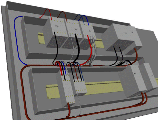
Example of a VRML output
