
Device Properties - Slots/Pins View for Pins
The Slots/Pins tab is only displayed when a device, with a model definition, is selected.
To display the properties (in Project mode),
-
With the required device selected in the Drawing Window, select Format->Device Properties from the Main Menu bar and select the Slots/Pins tab, or
-
right-click on a device on the drawing and select the Device Properties... command from the displayed context menu and select the Slots/Pins tab or
-
right-click on a device in the Device Tree View of the Project Window and select Device Properties... from the displayed context menu to display the Device Properties dialog box, and select the Slots/Pins tab.
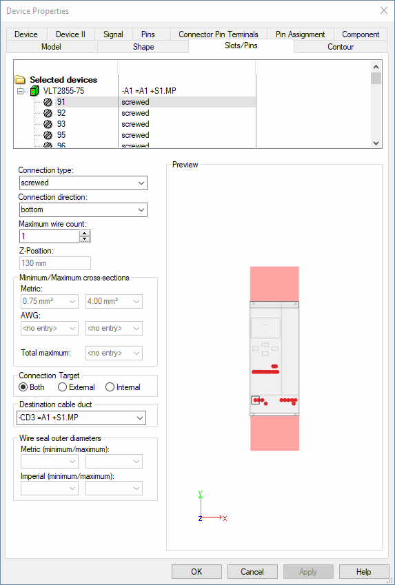
The top part of the dialog box displays a Tree View of all the Slots/Pins defined for the selected device. In the case of connect points, the connection type and connection direction are shown.
Where wires are already connected to connect points, the tree also shows the wire and the devices to which it is connected.
|
Slots/Pins |
|
|---|---|
|
Connection type |
The connection type (e.g. screwed, clamped or soldered, etc.) of a model defined in the database can be specified for a pin, and changed afterwards in Project mode.
The 'type' (electric, hydraulic, pneumatic) of the 'Connection Type' (the assignment takes place in Database Editor Mode under Format -> Connection Types...), cannot be changed. It may only be exchanged by a 'connection type' of the same type.
NoteThe new 'connection type' must exist in the database or in the project.
Nodes of the type Busbar cannot be assigned or modified for existing components afterwards.
The connection direction of nodes of the type Busbar is Connect all directions and cannot be changed. |
|
Connection direction |
Right: When routing a wire, the system searches for the cable duct at the right side of the pin.
Top: When routing a wire, the system searches for the cable duct above the pin.
Bottom: When routing a wire, the system searches for the cable duct below the pin.
Left: When routing a wire, the system searches for the cable duct at the left side of the pin.
Vertical: When routing a wire, the system searches for the cable duct above or below the pin (shortest distance).
Horizontal: When routing a wire, the system searches for the cable duct at the left or right side of the pin (shortest distance).
All: When routing a wire, the system searches for all possible routing paths and then selects the cable duct through which the shortest wire is created.
Automatic: The connection direction corresponds to the position of the pin.
When the pin is placed above the model's center, the system searches for the cable duct above the pin.
When the pin is placed below the model's center, the system searches for the cable duct below the pin. |
|
Maximum wire count |
Defines the maximum number of conductors/wires connectable to model pins.
The lower limit value can be set to the number of already connected conductors/wires at the most.
NoteThe maximum number of cores is calculated by the current active Variants/Options constellation at Variants/Options. |
|
Maximum connection count |
This option is only available with hydraulic or pneumatic connection types!
Defines the maximum number of connections for hoses/tubes. |
|
Z-Position |
Defines the position in Z direction of the selected pin in relation to the base. |
Minimum/Maximum cross-sections |
|
|
|
NoteRegarding the Conductor Assignment Procedure of conductors/wires, please consider the following:
If a metric as well as an AWG value is defined for the min./max. cross-section, the following is valid:
|
|
Metric / AWG |
Defines the maximum and minimum cross-section in both metric units and AWG. |
|
Total maximum |
Defines the total maximum cross-sectional area connected to the pin.
NoteRegarding the Conductor Assignment Procedure of conductors/wires, please consider the following:
If a metric as well as an AWG value is defined for the min./max. cross-section, the following is valid:
|
Connection TargetThis option permits the user to define which pin is internal or external and thereby ensures the pin is correctly routed
See also: Connection Target |
|
|
Both |
The attributes are not considered when routing, all wires can be connected here. |
|
External |
Wires with the "External connection" attribute (.EXTERN) are routed to these pins. When no free pin with this setting is available, the wire is routed to the next free pin with target Both. |
|
Internal |
Wires with the "Internal connection" attribute (.INTERN) are routed to these pins. When no free pin with this setting is available, the wire is routed to the next free pin with target Both. |
|
Destination cable duct |
With this option, a destination cable duct can be defined for the selected pin. The drop-down list contains all cable ducts available in the project.
NoteWhen such a definition exists, always this cable duct is used (exception: restrictions are placed in between, the cable duct is blocked or restriction violations exist between the cable duct's conductor or signal).
It is also used, when the first connection part is not placed lineally to the cable duct. Which connection direction is used, does not matter. |
Wire seal outer diameterThis option is only available with wire seal connection types! |
|
|
Metric (Minimum/Maximum) |
Defines a maximum and minimum default outer diameter for the wire seal in metric ( |
|
Imperial (Minimum/Maximum) |
Defines a maximum and minimum default outer diameter for the wire seal in imperial (inch) units. |
|
Preview |
Displays a schematic image showing position and size of the selected component and the location of the pins.
The selected pin is highlighted in the preview. |
Variants/OptionsThis part of the dialog is only displayed if variants/options have been defined in the project and the Standard Mode is active, but is inactive with this tab. |
|