Connector Symbol Definition
To define a connector component a symbol is required describing the connector.
-
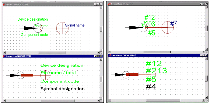
This symbol defines the element, which is used for the connector when placing single or multiple pins of the connector on the sheet. The same symbol is used for single and multiple pin representation. The symbol bears one pin for electrical connections, and several wires/coresconductors can be connected to the same pin, if this 'logical' pin is representing several physical pins.
It is possible to define several additional symbols, depending on the connector's functionality.
-
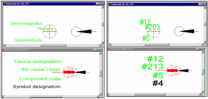
This symbol is used to place the connector on a block. The same symbol is used for single and multiple pin representation. The symbol bears one pin for electrical connections, and several wires/coresconductors can be connected to the same pin, if this 'logical' pin is representing several physical pins.
-
Symbols for other connector views
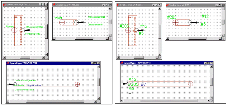
These symbols can be used to place another connector view. Several symbols may exist; the user can dynamically select one of the symbols to place another connector view in project. The same symbol is used for single and multiple pin representation. This is exactly the same symbol type and definition as the 'connector symbol'.
-
Master symbol
This symbol is used as a documentary graphic for the connector. The symbol does not require a pin or any other specific text node. The Place Documentation Graphic command places the symbol. The symbol, i.e. the connector will be displayed in the Preview window when selected in the Database window.
When defining a connector, the connector's mating connectors can be defined. This can be done in the Component Properties dialog box. As soon as an electrical connection is created, one of the defined mating connectors is used for the electrical connection. The mating connector needs to be a connector component which has already been defined in the database.
When switching connectors, only those connectors can be defined that match the defined mating connectors.
Note
Connectors that do not have valid mating connectors defined, cannot be selected when switching components.
Defining a Connector Symbol
This symbol has to be defined in a special way in the symbol database. It has to be defined that the symbol will be plugged to the left side and the electrical connection will run to the right. This special definition is required as the symbol has to be automatically adjusted and rotated, if it is placed as counterpart of another connector.
1. Origin
The origin's coordinates are used for the start point of the electrical connection. The origin has to be defined on the right side of the pin.
2. Pin
The pin serves for automatic placement of the connector, if the connector is used as mating connector. If the connector is used as base component, the coordinates of the pin are used for placing the mating connector, i.e. the pins of two components (base component and mating connector) are placed on the same coordinates.
The pin has to be defined on the left side of the origin and can be connected from left.

Defining a Block Symbol
This symbol has to be defined in a special way in the symbol database. It has to be defined that the symbol will be placed on the right side of the block. This special definition is required as the symbol has to be automatically adjusted and rotated, if it is placed as mating connector of another connector.
1. Origin
The origin is used for placing the symbol on the block's borders. The origin has to be defined on the left side of the pin.
2. Pin
The pin serves for automatic placement of the mating connector. The coordinates of the pin are used for placing the mating connector, i.e. the pins of two components (block symbol and mating connector) are placed on the same coordinates.
The pin has to be defined on the right side of the origin and can be connected from right.

Defining a Symbol for other Connector Views
This symbol is defined exactly in the same way as the 'connector symbol'.
The symbol looks like the mechanical representation of the connector and is placed as one symbol for all pins (pin group) or as a table, which is used to display, for example, the signal for each pin of the connector (single pin representation).
