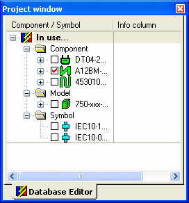
Project Window in Database Editor mode
In Project mode, the Project Window consists of several tabs (e.g. Sheet, Devices etc.; find more information under Interface Elements.
In Database Editor mode, however, the Project Window consists of one tab only, namely the Database Editor tab that displays all components, symbols and models that are currently in use.
Clicking on any part in the sub-tree will display the corresponding symbol in the Preview Window. Double-clicking on a part in the Tree will open up the sheet, on which it is located, and highlight the part.

Click in the '+' box (or double-click on the folder name) of the Component folder to open a sub-tree with normal devices, connectors and cables.
-
Devices in the DBE Tree View: The sub-tree shows all symbols that belong to that device
-
Connectors in the DBE Tree View: Connectors can either be placed freely or on blocks. Different views or documentation symbols can be placed for connectors. These different possibilities are represented correspondingly in the tree (see above image).
-
Cables in the DBE Tree View: The structure of a cable can be modified using the Drag&Move functionality in the tree. Modifications in the tree are immediately reflected in the working area of the Database Editor. A ban cursor is displayed if you attempt an invalid operation. Shields, twisted pairs and bundles that cover no conductor are only displayed in the Tree View, but not on the component sheet. As soon as a conductor is added to the shield, twisted pair or bundle, e.g. Drag&Drop functionality, it is also displayed on the component sheet.
Click in the '+' box (or double-click on the folder name) of the Symbol folder to open a sub-tree with all symbols currently in use.